Sign In
Upload
Manuals
Brands
Toshiba Manuals
Computer Hardware
H9
Toshiba H9 Manuals
Manuals and User Guides for Toshiba H9. We have
2
Toshiba H9 manuals available for free PDF download: Installation And Operation Manual, Quick Start Manual
Toshiba H9 Installation And Operation Manual (289 pages)
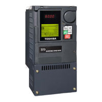
Toshiba Adjustable Speed Drive Installation and Operation Manual
Brand:
Toshiba
| Category:
Computer Hardware
| Size: 6.3 MB
Table of Contents
Important Notice
4
About this Manual
5
Table of Contents
7
General Safety Information
9
Safety Alert Symbol
9
Signal Words
9
Special Symbols
10
Equipment Warning Labels
10
Qualified Personnel
10
Equipment Inspection
11
Handling and Storage
11
Disposal
11
Installation Precautions
12
Location and Ambient Requirements
12
Mounting Requirements
12
Conductor Routing and Grounding
13
Grounding Capacitor Switch
13
Power Connections
14
Protection
14
System Integration Precautions
15
Personnel Protection
15
System Setup Requirements
16
Operational and Maintenance Precautions
17
Motor Characteristics
18
Motor Autotuning
18
Pulse Width Modulation Operation
18
Low Speed Operation
18
Overload Protection Adjustment
18
Operation above 60 Hz
18
Power Factor Correction
19
Light Load Conditions
19
Motor/Load Combinations
19
Load-Produced Negative Torque
20
Motor Braking
20
H9 ASD Characteristics
21
Over-Current Protection
21
ASD Capacity
21
Using Vector Control
21
Installation and Connections
22
Installation Notes
22
Mounting the H9 ASD
23
Connecting the H9 ASD
24
Power Connections
24
System Grounding
26
Lead Length Specifications
28
I/O and Control
29
Terminal Descriptions
30
I/O Circuit Configurations
33
Typical Connection Diagram
34
Startup and Test
35
Electronic Operator Interface
36
EOI Operation
36
EOI Remote Mounting
36
EOI Features
37
LED Display
38
LCD Display
39
Keypad Remote Mounting
41
Remote Keypad Required Hardware
41
Keypad Installation Precautions
41
Keypad Remote Mounting W/O the ASD-MTG-KIT
42
Keypad Remote Mounting Using the ASD-MTG-KIT
43
Command Mode and Frequency Mode Control
44
Command Control (F003)
44
Frequency Control (F004)
45
Command and Frequency Control Selections
45
Override Operation
46
Command and Frequency-Control Override Hierarchy
46
Command Control Selections
47
Frequency Control Selections
47
System Configuration and Menu Options
49
Root Menus
49
Frequency Command Mode
49
Monitor Mode
51
Program Mode Menu Navigation
54
Accel/Decel #1 Settings
54
Frequency Settings
54
Analog Output Terminals
55
Input Special Functions
55
Output Terminals
57
Reach Settings
57
Abnormal Speed Settings
60
Overtorque Parameters
61
Phase Loss
61
Analog Filter
62
Jog Settings
62
Acc/Dec Special
64
Carrier Frequency
64
Frequency Control
65
Operation Panel Parameters
66
Vector Motor Model
67
Override Control
69
Pg Settings
69
Communication Adjustments
72
Password Lockout
77
System Operation
78
Initial Setup
78
Startup Wizard Parameters
78
Startup Wizard Parameter Requirements
79
Voltage and Frequency Rating of the Motor
79
Automatic Acceleration/Deceleration
79
Command Source
80
Frequency Reference Source
80
Operation (Local)
81
Wizard Finish
81
Default Setting Changes
82
Save User Settings
83
Direct Access Parameter Information
84
Direct Access Parameters/Numbers
84
Command Mode
85
Base Frequency
89
V/F Pattern
89
Manual Torque Boost
90
Motor Overload Protection Configuration
90
Automatic Function Selection
93
Low-Speed Signal Output Frequency
94
Input Terminal 4 (Res) Function
97
Input Terminal 5 (S1) Function
97
Input Terminal 6 (S2) Function
97
Input Terminal 7 (S3) Function
97
Input Terminal 8 (S4) Function
97
Input Terminal 9 (Li1) Function
98
Input Terminal 10 (Li2) Function
98
Input Terminal 11 (Li3) Function
98
Input Terminal 12 (Li4) Function
99
Input Terminal 13 (Li5) Function
99
Input Terminal 14 (Li6) Function
99
Input Terminal 15 (Li7) Function
100
Input Terminal 16 (Li8) Function
100
Output Terminal 6 (R1) Function
102
Output Terminal 7 (Out5) Function
102
Output Terminal 9 (R2) Function
103
Input Terminal 1 (F) Response Time
103
Input Terminal 4 (Res) Response Time
104
Input Terminal 5 – 12 Response Time
104
Input Terminal 19 (B14) Function
105
Input Terminal 20 (B15) Function
105
Output Terminal 10 (R3) Function
105
Frequency Priority Selection
112
V/I Input Point 1 Setting
113
V/I Input Point 1 Frequency
114
V/I Input Point 2 Setting
114
V/I Input Point 2 Frequency
114
V/I Input Point 1 Rate
115
V/I Input Point 2 Rate
116
Frequency Mode Priority Switching Frequency
116
Analog Input Filter
117
Rr Input Point 1 Setting
118
Rr Input Point 1 Frequency
118
Rr Input Point 2 Setting
119
Rr Input Point 2 Frequency
119
Rr Input Point 1 Rate
120
Rr Input Point 2 Rate
120
Rx Input Point 1 Setting
121
Rx Input Point 1 Frequency
121
Rx Input Point 2 Setting
122
Rx Input Point 2 Frequency
122
Rx Input Point 1 Rate
123
Rx Input Point 2 Rate
123
Rx2 (Ai1) Input Point 1 Setting
124
Rx2 (Ai1) Input Point 1 Frequency
125
Rx2 (Ai1) Input Point 2 Setting
125
Rx2 (Ai1) Input Point 2 Frequency
125
Rx2 (Ai1) Input Point 1 Rate
126
Rx2 (Ai1) Input Point 2 Rate
127
Bin Input Point 1 Setting
128
Bin Input Point 1 Frequency
129
Bin Input Point 2 Setting
129
Bin Input Point 2 Frequency
129
Pg Input Point 2 Setting
131
Pg Input Point 2 Frequency
131
Run Frequency Hysteresis
132
Hz Dead Band Signal
132
DC Injection Braking Time
133
Hz Command Output
133
Jog Frequency
134
Jog Stop Pattern
135
Panel Operation Jog Mode
135
Jump Frequency 1 Bandwidth
139
Jump Frequency 2 Bandwidth
139
Overvoltage Limit Operation
144
Synchronized Acceleration Time
147
Drooping Gain
147
Speed at 0% Drooping Gain
147
Speed at F320 Drooping Gain
147
Drooping Insensitive Torque
148
Drooping Output Filter
148
Light-Load High-Speed Operation
148
Light-Load High-Speed Learning Function
148
Light-Load High-Speed Operation Load Wait Time
149
Light-Load High-Speed Operation Detection Time
149
Torque Bias Input Selection
151
Panel Torque Bias
151
Panel Torque Gain
151
Release Time
151
Creeping Frequency
151
Creeping Time
152
Braking Time Learning Function
152
Acceleration Suspend Frequency
153
Acceleration Suspend Time
153
Deceleration Suspend Frequency
153
Deceleration Suspend Time
153
Pid Feedback Signal
156
Pid Feedback Delay Filter
156
Pid Deviation Upper Limit
156
Pid Deviation Lower Limit
157
Process Upper Limit
157
Process Lower Limit
157
Pid Control Wait Time
157
Pid Output Upper Limit
157
Pid Output Lower Limit
158
Process Increasing Rate
158
Process Decreasing Rate
158
Number of Pg Input Pulses
158
Number of Pg Input Phases
158
Pg Disconnection Detection
159
Simple Positioning Completion Range
159
Slip Frequency Gain
159
Motor Rated Capacity
160
Motor Rated Current
160
Motor Rated Rpm
160
Motor Constant 1 (Torque Boost)
161
Motor Constant 3 (Leak Inductance)
161
Motor Constant 4 (Rated Slip)
161
Stall Prevention Factor
162
Torque Command Selection
162
Tension Torque Bias Input
162
Load Sharing Gain Input
163
Forward Speed Limit Input
163
Reverse Speed Limit Input
164
Reverse Speed Limit Input Level
164
Speed Limit (Torque=0) Center Value Reference
164
Speed Limit (Torque=0) Band
165
Power Running Torque Limit
165
Power Running Torque Limit 1 Level
165
Regenerative Braking Torque Limit
166
Regenerative Braking Torque Limit 1 Level
166
Power Running Torque Limit 2 Level
166
Regenerative Braking Torque Limit 2 Level
166
Power Running Torque Limit 3 Level
166
Regenerative Braking Torque Limit 3 Level
167
Power Running Torque Limit 4 Level
167
Regenerative Braking Torque Limit 4 Level
167
Power Running Stall Continuous Trip Detection Time
167
Stall Prevention During Regeneration
168
Current Control Proportional Gain
168
Speed Loop Proportional Gain
168
Speed Loop Stabilization Coefficient
168
Second Speed Loop Proportional Gain
168
Second Speed Loop Stabilization Coefficient
169
Speed Pid Switching Frequency
169
V/I Input Bias
169
V/I Input Gain
169
Rr Input Bias
170
Rr Input Gain
170
Rx Input Bias
170
Rx Input Gain
170
Rx2 (Ai1) Input Bias
171
Rx2 (Ai1) Input Gain
171
Pattern 1 Repeat
179
Pattern Group 1 Selection
180
Speed 1 Operation Time
185
Speed 2 Operation Time
185
Speed 3 Operation Time
185
Speed 4 Operation Time
185
Speed 5 Operation Time
185
Speed 6 Operation Time
185
Speed 7 Operation Time
186
Speed 8 Operation Time
186
Speed 9 Operation Time
186
Speed 10 Operation Time
186
Speed 11 Operation Time
186
Speed 12 Operation Time
186
Speed 13 Operation Time
187
Speed 14 Operation Time
187
Speed 15 Operation Time
187
Preset Speed 1 Operation Mode
188
Preset Speed 2 Operation Mode
188
Preset Speed 4 Operation Mode
189
Preset Speed 5 Operation Mode
189
Preset Speed 14 Operation Mode
190
Preset Speed 15 Operation Mode
190
Overload Reduction Starting Frequency
192
Asd Input Phase Failure Detection
192
Overtorque Detection Level (Negative Torque)
194
Abnormal Speed Detection Time
195
Over-Speed Detection Frequency Upper Band
195
Undervoltage Trip Detection Time
196
Regenerative Power Ridethrough Control Level
196
Asd Overload
197
Adding Input Selection
201
Multiplying Input Selection
201
Display Bias
208
Change Step Selection
208
Panel Frequency Lockout
210
Panel Emergency off Lockout
210
Trace Selection
211
Trace Cycle
211
Asd Number
213
Frequency Point Selection
215
Point 1 Setting
215
Point 2 Setting
216
Point 2 Frequency
216
Rs485 4-Wire Protocol Selection (Tsb/Modbus)
217
Disconnection Detection Extended Time
220
Asd Operation at Disconnect
220
Block Write Data
221
Block Read Data
222
My Function Percent Data
227
My Function Time Data
229
My Function Count Data
230
Analog Input Function Target
236
Virtual Input Terminal 1 Selection
240
Virtual Input Terminal 2 Selection
240
My Function Selection
241
Traverse Selection
243
Traverse Acceleration Time
243
Alarms, Trips, and Troubleshooting
254
Alarms and Trips
254
User Notification Codes
255
Alarms
255
Trips/Faults
258
Viewing Trip Information
263
Clearing a Trip
263
Enclosure Dimensions and Conduit Plate Information
264
Enclosure Dimensions
264
Current/Voltage Specifications
271
Cable/Terminal/Torque Specifications
273
Short Circuit Protection Recommendations
275
Dynamic Braking Resistor Wire/Cable Specifications
276
H9 ASD Optional Devices
278
Advertisement
Toshiba H9 Quick Start Manual (100 pages)
Adjustable Speed Drive
Brand:
Toshiba
| Category:
Inverter
| Size: 1.9 MB
Table of Contents
Table of Contents
6
Quick Start Guide
1
Important Notice
3
About this Guide
4
General Safety Information
8
Safety Alert Symbol
8
Signal Words
8
Special Symbols
9
Equipment Warning Labels
9
Qualified Personnel
9
Equipment Inspection
10
Handling and Storage
10
Disposal
10
Installation Precautions
11
Location and Ambient Requirements
11
Mounting Requirements
11
Conductor Routing and Grounding
12
Power Connections
13
Protection
13
System Integration Precautions
14
Personnel Protection
14
System Setup Requirements
15
Operational and Maintenance Precautions
16
Installation and Connections
17
Installation Notes
17
Mounting the ASD
18
Enclosure and Conduit Plate Dimensions
18
Connecting the ASD
19
System Grounding
21
Lead Length Specifications
23
I/O and Control
24
Startup and Test
30
Electronic Operator Interface
31
EOI Operation
31
Battery Backup
31
EOI Remote Mounting
32
EOI Features
33
System Configuration and Menu Options
36
Root Menus
36
Monitor Mode
38
Drooping Control
55
System Operation
65
Initial Setup
65
Startup Wizard Parameters
65
Operation (Local)
68
Default Setting Changes
69
Save User Settings
70
Alarms, Trips, and Troubleshooting
71
Alarms and Trips
71
User Notification Codes
72
Alarms
73
Trips/Faults
75
Enclosure and Conduit Plate Dimensions
81
Enclosure Dimensions
81
15.7/399 53.1/1349
82
Height Depth (In/MM) (In/MM)
82
Mounting Hole Dimensions (In/MM)
82
D E R1 R2
82
Figure 30-A
82
Figure 30-B
82
Figure 30-D
82
Conduit Plate Dimensions
86
7 B
82
Model Number VT130H9U
82
Enclosure Figure
82
Figure 27
82
Current/Voltage Specifications
89
Cable/Terminal/Torque Specifications
91
Short Circuit Protection Recommendations
93
Dynamic Braking Resistor Wire/Cable Specifications
94
Advertisement
Related Products
Toshiba HDTS106XZSWA
Toshiba HDTS112XZSWA
Toshiba HDTS124XZSWA
Toshiba TEC H-9100N-US
Toshiba TEC H-9100N-CA
Toshiba H9 ASD
Toshiba HD-A3KC
Toshiba HDTC610XS3A1
Toshiba HDTD105X53D1
Toshiba HD-A2WK
Toshiba Categories
Laptop
Air Conditioner
TV
LCD TV
All in One Printer
More Toshiba Manuals
Login
Sign In
OR
Sign in with Facebook
Sign in with Google
Upload manual
Upload from disk
Upload from URL