Sign In
Upload
Manuals
Brands
Panasonic Manuals
Accessories
HG-S Series
Panasonic HG-S Series Manuals
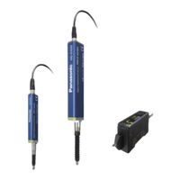
Manuals and User Guides for Panasonic HG-S Series. We have
6
Panasonic HG-S Series manuals available for free PDF download: User Manual, Instruction Manual
Panasonic HG-S Series User Manual (176 pages)
Contact-Type Digital Displacement Sensor
Brand:
Panasonic
| Category:
Security Sensors
| Size: 19.53 MB
Table of Contents
Table of Contents
4
Chapter 1 INTRODUCTION
7
Safety Cautions
8
Safety Information
8
Chapter 2 BEFORE USING this PRODUCT
11
Contents of Package
12
Description of Parts
16
Controller
16
Sensor Head
18
Sensor Head Connection Cable
18
Chapter 3 INSTALLATION and CONNECTIONS
19
Mounting the Controller
20
Mounting on a DIN Rail
20
Removing from a DIN Rail
20
Attaching the Sensor Head
21
Wiring the Controller Connector on the Sensor Head Connection Cable
23
Disassembly Procedure
23
Wiring Procedure
23
Connecting the Controller and Sensor Head
25
Attaching the Sensor Head and Sensor Head Connection Cable
25
Removing the Sensor Head and Sensor Head Connection Cable
26
Attaching the Controller and Sensor Head Connection Cable
27
Removing the Controller and Sensor Head Connection Cable
27
Connecting Controllers
28
Connection Method
28
Removal Method
29
Connection Diagrams and I/O Circuit Diagrams
30
Connection Diagrams
30
I/O Circuit Diagrams
32
Chapter 4 BASIC OPERATION
39
Explanation of Basic Operation
40
From Power on to Mode Selection
40
Operation Keys and Display
41
Operation Keys
41
Display
42
Explanation of Modes
43
Display Switching Mode
43
Presets
46
Teaching Mode
49
HIGH Set Value Fine Adjustment Function and LOW Set Value Fine Adjustment Function
56
Bank Mode
58
How to Save and Load Settings to / from a Bank
58
Setting Items Saved to and Loaded from Banks
58
Saving and Loading by Operation Key
59
Loading by External Input
61
Key Lock
62
Chapter 5 FUNCTION SETTINGS
65
Overview of Setting Menu
66
Menu Structure
66
Data Flow
68
Setting Items and Default Values
69
Setting Items and Default Values ·5-5
69
Basic Settings
72
HIGH Set Value
73
HIGH Set Value ( )
73
LOW Set Value
74
LOW Set Value ( )
74
Hysteresis
75
Hysteresis ( )
75
Teaching Types
77
Teaching Types ( )
77
Tolerance
79
Tolerance <±> ( )
79
Preset Value
80
Preset Value ( )
80
Preset Data Selection
81
Preset Data Selection ( 5-2-8 Preset Save ( )
81
Preset Save
82
Measurement Direction
83
Measurement Direction ( )
83
Lever Ratio
85
Lever Ratio ( )
85
Response Time
86
Response Time ( )
86
Output Operation
88
Output Operation ( 5-3 Advanced Settings ( )
88
Advanced Settings
89
Hold Setting
90
Hold Setting ( )
90
Measurement Modes
90
Measurement Modes ( )
90
Sample Hold
91
Peak to Peak Hold / 2
92
Peak Hold, Bottom Hold, Peak to Peak Hold, Peak to Peak Hold / 2 ·5-30 5-3-1-1-3 NG Hold
94
NG Hold
97
Self Sample Hold (Delay Timer)
99
Self Sample Hold (Static Width)
102
Self Peak Hold / Self Bottom Hold
105
Input All ( ) (Master Unit Only)
109
External Input
111
External Input ( )
111
External Output
113
External Output ( )
113
Number of Digits Displayed
116
Number of Digits Displayed ( )
116
Analog Scaling
117
Analog Scaling ( )
117
Scaling Upper Limit Value / Scaling Lower Limit Value
119
Eco Mode
122
Eco Mode ( )
122
Alarm Setting
123
Alarm Setting ( )
123
Pressure Check / Pressure Check Set
123
Value / Alarm Delay Count
125
Pressure Check / Pressure Check Set Value / Alarm Delay Count · 5-60 5-3-9-2 Catch Check
126
Catch Check
128
Number of Connected Controllers Check (Master Unit Only)
130
Calculation Settings ( ) (Master Unit Only)
131
Calculation Settings
131
Calculation Settings ( (Master Unit Only)
131
Calculation Mode
132
Calculation Mode ( )
132
Calculation Application Selection
133
Calculation Application Selection ( )
133
Maximum Value
134
Maximum Value ( )
134
Flatness
135
Flatness ( )
135
Minimum Value
135
Minimum Value ( )
135
Average Value
136
Average Value ( )
136
Standard Difference
136
Torsion
137
Torsion ( )
137
Curvature
138
Curvature ( )
138
Thickness
139
Thickness ( )
139
Copy Settings
140
Copy Select Individual ( ) (Master Unit Only)
142
Copy Select All ( ) (Master Unit Only)
144
Copy Execution ( ) (Master Unit Only)
145
Copy Lock ( ) (Slave Units Only)
146
Copy Lock
146
(Slave Units Only)
146
Bank Settings
147
Bank Save Setting
147
Bank Save Setting ( 5-7 Calibration Settings ( )
147
Calibration Settings
149
Calibration Selection
149
Calibration Selection ( ) ·5-85
149
Initialization ( )
153
Initialization
153
Maintenance
155
Chapter 6 SPECIFICATIONS
157
Dimensions
161
Chapter 7 Appendix
165
Maintenance and Inspection
166
Maintenance Cautions
166
Main Inspection Items
166
Replacing the Probe
167
Replacing the Rubber Bellows
168
Error Messages
170
Troubleshooting
171
Advertisement
Panasonic HG-S Series User Manual (175 pages)
Contact-Type Digital Displacement Sensor
Brand:
Panasonic
| Category:
Accessories
| Size: 21.65 MB
Table of Contents
Table of Contents
4
Chapter 1 INTRODUCTION
7
Safety Cautions
8
Safety Information
8
Chapter 2 BEFORE USING this PRODUCT
11
Contents of Package
12
System Configuration
14
Description of Parts
15
Controller
15
Sensor Head
18
Sensor Head Connection Cable
18
Chapter 3 INSTALLATION and CONNECTIONS
19
Mounting the Controller
20
Mounting on a DIN Rail
20
Removing from a DIN Rail
20
Attaching the Sensor Head
21
Wiring the Controller Connector on the Sensor Head Connection Cable
23
Disassembly Procedure
23
Wiring Procedure
23
Connecting the Controller and Sensor Head
25
Attaching the Sensor Head and Sensor Head Connection Cable
25
Removing the Sensor Head and Sensor Head Connection Cable
26
Attaching the Controller and Sensor Head Connection Cable
27
Removing the Controller and Sensor Head Connection Cable
27
Connecting Controllers
28
Connection Method
28
Removal Method
29
Connection Diagrams and I/O Circuit Diagrams
30
Connection Diagrams
30
I/O Circuit Diagrams
32
Chapter 4 BASIC OPERATION
39
Explanation of Basic Operation
40
From Power on to Mode Selection
40
Operation Keys and Display
41
Operation Keys
41
Display
42
Explanation of Modes
43
Display Switching Mode
43
Presets
46
Teaching Mode
49
HIGH Set Value Fine Adjustment Function and LOW Set Value Fine Adjustment Function
56
Bank Mode
58
How to Save and Load Settings to / from a Bank
58
Setting Items Saved to and Loaded from Banks
58
Saving and Loading by Operation Key
59
Loading by External Input
61
Key Lock
62
Chapter 5 FUNCTION SETTINGS
65
Overview of Setting Menu
66
Menu Structure
66
Data Flow
68
Setting Items and Default Values
69
Setting Items and Default Values ·5-5
69
Basic Settings
72
HIGH Set Value
73
HIGH Set Value ( )
73
LOW Set Value
74
LOW Set Value ( )
74
Hysteresis
75
Hysteresis ( )
75
Teaching Types
77
Teaching Types ( )
77
Tolerance
77
Tolerance <±> ( )
77
Preset Value
80
Preset Value ( )
80
Preset Data Selection ( ) ·5-17
81
Preset Save
82
Preset Save ( )
82
Measurement Direction
83
Measurement Direction ( )
83
Lever Ratio
85
Lever Ratio ( )
85
Response Time
86
Response Time ( )
86
Output Operation
88
Output Operation ( 5-3 Advanced Settings ( )
88
Advanced Settings
89
Hold Setting
90
Hold Setting ( )
90
Measurement Modes
90
Measurement Modes ( )
90
Sample Hold
91
Peak to Peak Hold / 2
92
Peak Hold, Bottom Hold, Peak to Peak Hold, Peak to Peak Hold / 2 ·5-30 5-3-1-1-3 NG Hold
94
NG Hold
97
Self Sample Hold (Delay Timer)
99
Self Sample Hold (Static Width)
102
Self Peak Hold / Self Bottom Hold
105
(Master Unit Only)
109
Input All ( ) (Master Unit Only)
109
External Input
111
External Input ( )
111
External Output
113
External Output ( )
113
Number of Digits Displayed
115
Number of Digits Displayed ( )
115
Analog Scaling
116
Analog Scaling ( )
116
Scaling Upper Limit Value / Scaling Lower Limit Value
118
Eco Mode
121
Alarm Setting
122
Alarm Setting ( )
122
Pressure Check / Pressure Check Set Value
123
Alarm Delay Count
124
Pressure Check / Pressure Check Set
125
Catch Check
127
Number of Connected Controllers Check (Master Unit Only)
129
Calculation Settings ( ) (Master Unit Only)
130
Calculation Mode
131
Calculation Mode ( )
131
Calculation Application Selection
132
Calculation Application Selection ( )
132
Maximum Value
133
Maximum Value ( )
133
Flatness
134
Flatness ( )
134
Minimum Value
134
Minimum Value ( )
134
Average Value
135
Average Value ( )
135
Standard Difference
135
Torsion
136
Torsion ( )
136
Curvature
137
Curvature ( )
137
Thickness
138
Thickness ( )
138
Copy Settings
139
Copy Select Individual ( ) (Master Unit Only)
141
Copy Select All ( ) (Master Unit Only)
143
Copy Execution ( ) (Master Unit Only)
144
(Slave Units Only)
145
Copy Lock
145
Bank Settings
146
Bank Save Setting
146
Bank Save Setting ( 5-7 Calibration Settings ( )
146
Calibration Settings
148
Calibration Selection
148
Initialization ( )
152
Maintenance
154
Chapter 6 SPECIFICATIONS
157
Specifications
159
Dimensions
161
Chapter 7 Appendix
165
Maintenance and Inspection
166
Maintenance Cautions
166
Main Inspection Items
166
Replacing the Probe
167
Replacing the Rubber Bellows
168
Error Messages
170
Troubleshooting
171
Panasonic HG-S Series User Manual (200 pages)
Contact-Type Digital Displacement Sensor
Brand:
Panasonic
| Category:
Accessories
| Size: 22.07 MB
Table of Contents
Table of Contents
4
Chapter 1 INTRODUCTION
7
Safety Cautions
8
Safety Information
8
Chapter 2 BEFORE USING this PRODUCT
11
Contents of Package
12
System Configuration
16
Description of Parts
17
Controller
17
Sensor Head (Regular Type)
19
Sensor Head (Air-Driven Type)
19
Sensor Head Connection Cable
20
Chapter 3 INSTALLATION and CONNECTIONS
21
Mounting the Controller
22
Mounting on a DIN Rail
22
Removing from a DIN Rail
22
Attaching the Sensor Head
23
Wiring the Controller Connector on the Sensor Head Connection Cable
25
Disassembly Procedure
25
Wiring Procedure
25
Connecting the Controller and Sensor Head
27
Attaching the Sensor Head and Sensor Head Connection Cable
27
Removing the Sensor Head and Sensor Head Connection Cable
28
Connecting the Air Tube (Air-Driven Type Only)
29
Disconnecting the Air Tube (Air-Driven Type Only)
29
Air Circuit (Recommended) (Air-Driven Type Only)
30
Attaching the Controller and Sensor Head Connection Cable
31
Removing the Controller and Sensor Head Connection Cable
31
Connecting Controllers
32
Connection Method
33
Removal Method
35
Connection Diagrams and I/O Circuit Diagrams
36
Connection Diagrams
36
I/O Circuit Diagrams
38
Chapter 4 BASIC OPERATION
45
Explanation of Basic Operation
46
From Power on to Mode Selection
46
Operation Keys and Display
47
Explanation of Modes
49
Display Switching Mode
49
Presets
52
Teaching Mode
55
Bank Mode
64
Key Lock
68
Self-Monitoring Function
70
Using the Self-Monitoring Function
70
Statuses and Measures
71
Chapter 5 FUNCTION SETTINGS
73
Overview of Setting Menu
76
Menu Structure
76
Data Flow
78
Setting Items and Default Values
79
Basic Settings
82
HIGH Set Value
83
LOW Set Value
84
Hysteresis
85
Teaching Types
87
Tolerance
89
Preset Value
90
Preset Data Selection
91
Preset Save
92
Measurement Direction
93
Lever Ratio
95
Response Time
96
Output Operation
98
Advanced Settings
99
Hold Setting
100
Input All ( ) (Master Unit Only)
125
External Input
127
External Output
129
Number of Digits Displayed
132
Analog Scaling
133
Scaling Upper Limit Value / Scaling Lower Limit Value
135
Eco Mode
138
Alarm Setting
139
Calculation Settings ( ) (Master Unit Only)
148
Calculation Mode
149
Calculation Application Selection
150
Copy Settings
157
Copy Select Individual ( ) (Master Unit Only)
159
Copy Select All ( ) (Master Unit Only)
161
Copy Execution ( ) (Master Unit Only)
162
Copy Lock ( ) (Slave Units Only)
163
Bank Settings
164
Bank Save Setting
164
Calibration Settings
166
Calibration Selection
166
Initialization ( )
170
Maintenance
172
Chapter 6 SPECIFICATIONS
175
Specifications
177
Dimensions
182
Chapter 7 Appendix
189
Maintenance and Inspection
190
Maintenance Cautions
190
Main Inspection Items
190
Replacing the Probe
191
Replacing the Rubber Bellows (Regular Type Only)
192
Replacing the Seal Cap (Air-Driven Type Only)
194
How to Remove the Seal Cap
194
How to Mount the Seal Cap
194
Error Messages
195
Troubleshooting
196
Advertisement
Panasonic HG-S Series User Manual (198 pages)
Contact-Type Digital Displacement Sensor
Brand:
Panasonic
| Category:
Security Sensors
| Size: 12.79 MB
Table of Contents
Table of Contents
5
Before Using this Product
9
Safety Cautions (Always Observe)
10
Safety Information
11
Contents of Package
13
System Configuration and Description of Parts
17
System Configuration
18
Description of Parts
19
Controller
19
Sensor Head (Regular Type)
21
Sensor Head (Air-Driven Type)
22
Sensor Head Connection Cable
22
Installation and Connections
25
Mounting the Controller
26
Mounting on a DIN Rail
26
Removing from a DIN Rail
26
Attaching the Sensor Head
27
Wiring the Controller Connector on the Sensor Head Connection Cable
30
Disassembly Procedure
30
Wiring Procedure
30
Connecting the Controller and Sensor Head
33
Attaching the Sensor Head and Sensor Head Connection Cable
33
Removing the Sensor Head and Sensor Head Connection Cable
34
Connecting the Air Tube (Air-Driven Type Only)
34
Disconnecting the Air Tube (Air-Driven Type Only)
35
Air Circuit (Recommended) (Air-Driven Type Only)
35
Attaching the Controller and Sensor Head Connection Cable
35
Removing the Controller and Sensor Head Connection Cable
36
Connecting Controllers
37
Connection Method
38
Removal Method
40
Connection Diagrams and I/O Circuit Diagrams
41
Connection Diagrams
41
I/O Circuit Diagrams
42
Basic Operation
49
Explanation of Basic Operation
50
From Power on to Mode Selection
50
Operation Keys and Display
50
Explanation of Modes
53
Display Switching Mode
53
Preset
55
Teaching Mode
58
Bank Mode
65
Key Lock
68
Self-Monitoring Function
70
Using the Self-Monitoring Function
70
Statuses and Measures
71
Function Settings
73
Overview of Setting Menu
75
Menu Structure
75
Data Flow
76
Setting Items and Default Values
78
Basic Settings ( )
82
HIGH Set Value ( )
82
LOW Set Value
83
Hysteresis ( )
85
Teaching Types
87
Tolerance
88
Preset Value ( )
89
Preset Data Selection
90
Preset Save
91
Measurement Direction
92
Lever Ratio ( )
94
Response Time
95
Output Operation
96
Advanced Settings ( )
98
Hold Setting ( )
98
Input All ( ) (Master Unit Only)
123
External Input
125
External Output
127
Number of Digits Displayed ( )
130
Analog Scaling
131
Scaling Upper Limit Value / Scaling Lower Limit Value
133
Eco Mode ( )
136
Alarm Setting
137
Calculation Settings ( ) (Master Unit Only)
146
Calculation Mode
146
Calculation Application Selection
147
Copy Settings ( )
154
Copy Select Individual ( ) (Master Unit Only)
155
Copy Select All ( ) (Master Unit Only)
157
Copy Execution ( ) (Master Unit Only)
158
(Slave Units Only)
159
Copy Lock ( ) (Slave Units Only)
159
Bank Settings ( )
160
Bank Save Setting ( )
160
Calibration Settings
162
Calibration Selection
162
Initialization ( )
165
Maintenance
167
Specifications
169
Specifications
170
Dimensions
178
Controller
178
Contact-Type Digital Displacement Sensor
180
Appendix
185
Maintenance and Inspection
186
Maintenance Cautions
186
Main Inspection Items
186
Replacing the Probe
187
Replacing the Rubber Bellows (Regular Type Only)
188
Replacing the Seal Cap (Air-Driven Type Only)
190
How to Remove the Seal Cap
190
How to Mount the Seal Cap
190
Error Messages
192
Troubleshooting
194
Panasonic HG-S Series Instruction Manual (2 pages)
Contact-Type Digital Displacement Sensor / Sensor Head
Brand:
Panasonic
| Category:
Accessories
| Size: 0.37 MB
Panasonic HG-S Series Instruction Manual (2 pages)
Contact-Type Digital Displacement Sensor/Sensor Head
Brand:
Panasonic
| Category:
Security Sensors
| Size: 0.72 MB
Advertisement
Related Products
Panasonic HG-S1010R
Panasonic HG-SC101
Panasonic HG-SC111
Panasonic HG-SC111-P
Panasonic HG-SC112
Panasonic HG-SC112-P
Panasonic HG-SC113
Panasonic HG-S1010-AC
Panasonic HG-S1032
Panasonic HG-S1110
Panasonic Categories
Camcorder
Air Conditioner
TV
Digital Camera
Cordless Telephone
More Panasonic Manuals
Login
Sign In
OR
Sign in with Facebook
Sign in with Google
Upload manual
Upload from disk
Upload from URL