Sign In
Upload
Manuals
Brands
Canon Manuals
Copier
FC220
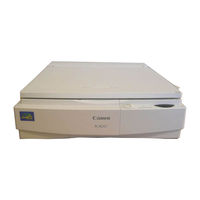
Canon FC220 Manuals
Manuals and User Guides for Canon FC220. We have
4
Canon FC220 manuals available for free PDF download: Service Manual, Service Handbook
Canon FC220 Service Manual (306 pages)
Brand:
Canon
| Category:
Copier
| Size: 3.41 MB
Table of Contents
Table of Contents
5
General Description
11
Chapter 1 General Description
12
Features
13
Specifications
14
Names of Parts
16
External View
16
Cross Section
17
Operation
18
Control Panel
18
Making Copies
20
Pc420/430/Fc220
21
Making Copies
22
Pc400/Fc200
22
Add Paper Indicator
23
Jam Indicator
23
Replacing the Cartridge
23
Changing the Density
26
Cleaning
26
Lens Array
27
When Not Using the Copier for a Long Time
28
Image Formation
29
Outline
29
Chapter 2 Basic Operation
31
Basic Operation
31
Outline
33
Basic Operation
33
Outline of Electrical Circuit
34
Basic Sequence of Operations (A4, 2 Copies)
35
Main Motor Control Circuit
37
Operation
37
Outline
37
Overcurrent Sensor
37
Inputs to DC Controller
38
Outputs from DC Controller
40
Chapter 3 Exposure System
43
Exposure/Copyboard Drive System
45
Outline of Exposure System
45
Copyboard Drive System
45
Outline
45
Controlling the Copyboard
47
Mechanism of Copyboard Drive Assembly
48
Controlling the Scanning Lamp
51
Outline
51
Operations
52
Controlling the Intensity of the Scanning Lamp (VR604)
52
Mechanical System
53
Detaching the Scanning Lamp
54
Scanning System
54
Detaching the Copyboard
55
Copyboard Drive Assembly
55
Chapter 4 Image Formation System
57
Image Formation System
57
Process Description
59
Outline
59
Sequence of Image Formation Operations (A4, 2 Copies)
60
Sequence of Image Formation
60
Primary Charging Control Circuit
61
Outline
61
Operations
62
Controlling Developing Bias
64
Outline
64
Operations
66
Transfer Charging Control Circuit
68
Outline
68
Operations
69
Document Density Measurement (AE; PC420/430/FC220)
72
Charging, Developing, and Cleaning Systems
75
Cartridge
75
Mechanical System
76
Photosensitive Drum
77
Transfer Charging Roller
78
Chapter 5 Pick-Up/Feeding System
79
Outline
81
Controlling the Pick-Up Roller
82
Pc420/430/Fc220
82
Pc400/Fc200
83
Controlling the Registration Roller
84
Outline
84
Pick-Up/Feeding Timing Chart (A4, 2 Copies)
85
Checking for Jams
86
Delivery Delay Jam
86
Pc400/Fc200
86
Pc420/430/Fc220
86
Delivery Stationary Jam
87
Pc400/Fc200
87
Pc420/430/Fc220
87
Pick-Up Delay Jam (PC420/430/FC220)
88
Pick-Up Stationary Jam
89
Pc400/Fc200
89
Pc420/430/Fc220
89
Paper Is Present at the Pick-Up or Delivery Sensor at Time of Power-On or When the Copy Start Key Is Pressed
89
Mechanical System
90
Pick-Up Roller Assembly
91
Detaching the Pick-Up Roller
91
Registration Roller Assembly
94
Detaching the Registration Roller Assembly
94
Removing the Separation Pad
95
Chapter 6 Fixing System
97
Fixing System
97
Outline of Operations
99
Outline
99
Controlling the Supply Power to the Fixing Heater
101
Controlling the Fixing Heater Temperature
101
Protection Mechanisms
103
Mechanical System
104
Fixing Assembly
105
Construction
105
Detaching the Fixing Assembly
105
Chapter 7 Externals/Auxiliary Mechanisms
111
Power Supply
113
Outline
113
Power Supply PCB
114
Protection Mechanism for Power Supply Circuit
114
II.mechanical System
115
Mechanical System
115
Detaching the Control Panel Cover
116
External Covers
116
Detaching the Body Cover
117
Detaching the Top Cover
119
Copyboard Assembly
121
DC Controller/DC Power Supply PCB
123
Control Panel PCB
126
Chapter 8 Installation
127
Selecting the Site
127
Unpacking and Installation
127
Chapter 9 Maintenance and Servicing
135
Durables
137
Periodical Servicing
137
Periodically Replaced Parts
137
Notes about Cartridge
138
Storing Sealed Cartridges
138
Storing and Handling Unsealed Cartridges
139
Storing Unsealed Cartridges
139
Handling the Cartridge
139
Chapter 10 Troubleshooting
143
Troubleshooting
143
Maintenance and Inspection
147
Image Adjustment Basic Procedure
147
Points to Note
148
Mechanical
149
Image Leading Edge Non-Image Width (Position of White Paint on Back of Glass)
149
Standards and Adjustments
149
Electrical
150
Adjusting the Intensity (VR604)
150
Adjusting the AE Mechanism (VR602, VR603)
152
Image Troubleshooting
155
Making Initial Checks
155
Checking the Documents
155
Site Environment
155
Checking the Copy Paper
156
Checking the Copyboard Cover and Copyboard Glass for Dirt and Scratches
156
Checking the Durables
156
Checking the Feeding Assembly
156
Checking the Lens Array for Dirt
156
Checking the Transfer Charging Roller
156
Others
158
Samples of Image Faults
160
Troubleshooting by Image Fault
161
The Copy Is too Light (Dark Areas as Well)
161
The Copy Is too Light (Extremely Light Overall)
161
The Copy Is too Light (Halftone Areas Only)
161
The Copy Has Uneven Density (Darker at Front)
162
The Copy Has Uneven Density (Lighter at Front)
162
The Copy Has Dark Lines (Paper Feed Direction, Relatively Narrow)
163
The Copy Has Dark Lines (Paper Feed Direction, Thin)
163
The Copy Has White Lines (Paper Feed Direction)
163
The Copy Has White Spots (Paper Feed Direction)
163
The Copy Is Foggy (Paper Feed Direction)
163
The Back of the Copy Is Soiled
164
The Copy Has White Spots
164
The Copy Has Faulty Fixing
165
The Copy Has Faulty Leading Edge Registration (Blank Area Much too Wide)
165
The Copy Has Faulty Leading Edge Registration (Blank Area too Wide)
165
The Copy Has Faulty Leading Edge Registration (no Blank Area)
165
The Copy Has a Blurred Image
166
The Copy Has Poor Sharpness (Focus)
166
The Copy Is Foggy (Cross Feed Direction)
166
The Copy Is Blank
167
The Copy Is Solid Black
167
Troubleshooting Malfunctions
168
(Self Diagnosis; PC400/FC200)
168
AC Power Is Absent
170
Pick-Up Fails
171
The Scanning Lamp Fails to Go on
171
The Main Motor Fails to Rotate
172
The Copyboard Fails to Move
172
(Paper Feeding Normally)
173
(At Time of Jam)
173
The Fixing Heater Fails to Operate
173
Troubleshooting Paper Feed Problems
174
Copy Paper Jams
174
Pick-Up Assembly
175
Separation/Feeding Assembly
175
Fixing/Delivery Assembly
176
Feeding Faults
177
Double Feeding
177
Wrinkles
177
Of Electrical Parts
178
Sensors and Solenoids
178
Switches
179
Lamp, Heater, Motor, and Others
180
Printed Circuit Board (PCB)10-37
181
Variable Resistors (VR) and Check Pins by PCB
182
Self Diagnosis
184
VII. Self Diagnosis
184
C. General Circuit Diagram...a
187
General Timing Chart
188
Signals/Abbreviations Lista-3
190
Signals
190
Abbreviations
191
Appendix
191
Special Tools Table
194
Solvents/Oils Table
195
Parts Catalog
198
Table of Contents
201
Assembly Location Diagram
202
Control Panel Assembly
221
Copyboard Cover Assembly
223
Copyboard Cover Assembly (Pc)
225
Copyboard Drive Assembly
227
Registration Roller Assembly
228
Paper Pick-Up Roller Assembly
230
Delivery Cover Assembly
231
List of Connectors
238
Table of Contents
247
Variable Resistors (VR) and
248
Chapter 1 Maintenance and Inspection
251
Durables
251
Periodical Servicing
251
Periodically Replaced Parts
251
Notes on Cartridge
252
Storing Sealed Cartridges
252
E. Image Adjustment Basic Procedure
255
Chapter 2 Standards and Adjustments
257
Mechanical
257
Image Leading Edge Margin (Point of Detection for Registration)
257
Image Leading Edge Non-Image Width (Position of White Paint on Back of Glass)
257
Chapter 3 Image Troubleshooting
263
Making Initial Checks
263
Checking the Documents
263
Site Environment
263
Checking the Copy Paper
264
Checking the Copyboard Cover and Copyboard Glass for Dirt and Scratches
264
Checking the Durables
264
Checking the Feeding Assembly
264
Checking the Transfer Charging Roller
264
Others
266
Samples of Image Faults
268
The Copy Is too Light (Extremely Light Overall)
269
Troubleshooting by Image Fault
269
Cartridges
269
The Copy Is too Light (Dark Areas as Well)
269
The Copy Is too Light (Halftone Areas Only)
269
The Copy Has Uneven Density (Darker at Front)
270
The Copy Has Uneven Density (Lighter at Front)
270
The Copy Is Foggy
270
The Copy Has Dark Lines (Paper Feed Direction, Relatively Narrow)
271
The Copy Has Dark Lines (Paper Feed Direction, Thin)
271
The Copy Has White Lines (Paper Feed Direction)
271
The Copy Has White Spots (Paper Feed Direction)
271
The Copy Has White Spots (Cross Feed Direction)
272
The Copy Has Faulty Fixing
273
The Copy Has Faulty Leading Edge Registration (Blank Area Much too Wide)
273
The Copy Has Faulty Leading Edge Registration (Blank Area too Wide)
273
The Copy Has Faulty Leading Edge Registration (no Blank Area)
273
Chapter 4 Troubleshooting Malfunctions
277
Troubleshooting Malfunctions
277
Self Diagnosis;Pc400/Fc200)
277
Pick-Up Fails
280
The Scanning Lamp Fails to Go on
280
DC Controller/DC Power
282
Chapter 5 Troubleshooting Paper Feed Problems
283
Copy Paper Jams
283
Pick-Up Assembly
284
Separation/Feeding Assembly
284
Fixing/Delivery Assembly
285
Chapter 6 Arrangement and Functions of Electrical Parts
287
Sensors and Solenoids
287
Switches
288
Lamp, Heater, Motor, and Others
289
Printed Circuit Board (PCB)
290
Control Panel Pcb
292
Control Panel PCB
294
DC Controller/DC Power Supply PCB
294
General Timing Chart
295
Signals/Abbreviations List
297
Signals
297
Abbreviations
298
Appendix
298
General Circuit Diagram
299
Special Tools Table
301
Solvents/Oils Table
302
Specifications
303
Advertisement
Canon FC220 Service Manual (197 pages)
Brand:
Canon
| Category:
Printer
| Size: 1.64 MB
Table of Contents
Table of Contents
5
General Description
11
Chapter 1 General Description
12
Features
13
Specifications
14
II. Specifications
14
Names of Parts
16
External View
16
Cross Section
17
Operation
18
Control Panel
18
Making Copies
20
Pc420/430/Fc220
21
Pc400/Fc200
22
Making Copies
22
Jam Indicator
23
Add Paper Indicator
23
Replacing the Cartridge
23
Replacing the Cartridge
24
Changing the Density
26
Cleaning
26
Copyboard Glass/Copyboard Cover
26
Lens Array
27
Pick-Up Roller
28
When Not Using the Copier for a Long Time
28
Image Formation
29
Outline
29
Chapter 2 Basic Operation
31
Basic Operation
31
Basic Operation
33
Outline
33
Outline of Electrical Circuit
34
Basic Sequence of Operations (A4, 2 Copies)
35
Main Motor Control Circuit
37
Outline
37
Operation
37
Overcurrent Sensor
37
Inputs to DC Controller
38
Outputs from DC Controller
40
Chapter 3 Exposure System
43
Exposure/Copyboard Drive System
45
Outline of Exposure System
45
Copyboard Drive System
45
Outline
45
Controlling the Copyboard
47
Mechanism of Copyboard Drive Assembly
48
Controlling the Scanning Lamp
51
Outline
51
Operations
52
Controlling the Intensity of the Scanning Lamp (VR604)
52
Mechanical System
53
Detaching the Scanning Lamp
54
Scanning System
54
Detaching the Copyboard
55
Copyboard Drive Assembly
55
Chapter 4 Image Formation System
57
Image Formation System
57
Outline
59
Process Description
59
Sequence of Image Formation
60
Sequence of Image Formation Operations (A4, 2 Copies)
60
Primary Charging Control Circuit
61
Outline
61
Operations
62
Controlling Developing Bias
64
Outline
64
Operations
66
Transfer Charging Control Circuit
68
Outline
68
Operations
69
Document Density Measurement (AE; PC420/430/FC220)
72
Operations
72
Cartridge
75
Charging, Developing, and Cleaning Systems
75
Outline
75
III.mechanical System
76
Photosensitive Drum
77
Cleaning the Drum
77
Transfer Charging Roller
78
Chapter 5 Pick-Up/Feeding System
79
Outline
81
Controlling the Pick-Up Roller
82
Pc420/430/Fc220
82
Pc400/Fc200
83
Controlling the Registration Roller
84
Outline
84
Pick-Up/Feeding Timing Chart (A4, 2 Copies)
85
Checking for Jams
86
Delivery Delay Jam
86
Pc420/430/Fc220
86
Pc400/Fc200
86
Delivery Stationary Jam
87
Pc420/430/Fc220
87
Pc400/Fc200
87
Pick-Up Delay Jam (PC420/430/FC220)
88
Pick-Up Stationary Jam
89
Pc420/430/Fc220
89
Pc400/Fc200
89
Paper Is Present at the Pick-Up or Delivery Sensor at Time of Power-On or When the Copy Start Key Is Pressed
89
Mechanical System
90
Pick-Up Roller Assembly
91
Detaching the Pick-Up Roller
91
Registration Roller Assembly
94
Detaching the Registration Roller Assembly
94
Removing the Separation Pad
95
Chapter 6 Fixing System
97
Fixing System
97
Outline of Operations
99
Outline
99
Controlling the Supply Power to the Fixing Heater
101
Controlling the Fixing Heater Temperature
101
Protection Mechanisms
103
Mechanical System
104
Fixing Assembly
105
Construction
105
Detaching the Fixing Assembly
105
Removing the Fixing Upper Unit
107
Chapter 7 Externals/Auxiliary Mechanisms
111
Power Supply
113
Outline
113
Power Supply PCB
114
Protection Mechanism for Power Supply Circuit
114
II.mechanical System
115
External Covers
116
Detaching the Control Panel Cover
116
Detaching the Body Cover
117
Detaching the Top Cover
119
Detaching the Delivery Assembly Cover
119
Copyboard Assembly
121
Detaching the Copyboard Cover
121
DC Controller/DC Power Supply PCB
123
Points to Note When Installing the Delivery Door Switch
125
Control Panel PCB
126
Chapter 8 Installation
127
III. Relocating the Machine
127
Chapter 9 Maintenance and Servicing
135
Selecting the Site
127
Unpacking and Installation
127
Durables
137
II. Durables
137
Periodical Servicing
137
Periodically Replaced Parts
137
Notes about Cartridge
138
Storing Sealed Cartridges
138
Storing Unsealed Cartridges
139
Storing and Handling Unsealed Cartridges
139
Handling the Cartridge
139
Chapter 10 Troubleshooting
143
A. Image Adjustment Basic Procedure
143
Maintenance and Inspection
147
Image Adjustment Basic Procedure
147
Points to Note
148
Standards and Adjustments
149
Mechanical
149
Electrical
150
Adjusting the Intensity (VR604)
150
Adjusting the AE Mechanism (VR602, VR603)
152
Making Initial Checks
155
Site Environment
155
Checking the Documents
155
Checking the Copyboard Cover and Copyboard Glass for Dirt and Scratches
156
Checking the Lens Array for Dirt
156
Checking the Transfer Charging Roller
156
Checking the Feeding Assembly
156
Checking the Copy Paper
156
Checking the Durables
156
Others
158
Samples of Image Faults
160
Troubleshooting by Image Fault
161
The Copy Is too Light (Halftone Areas Only)
161
The Copy Is too Light (Dark Areas as Well)
161
The Copy Is too Light (Extremely Light Overall)
161
The Copy Has Uneven Density (Darker at Front)
162
The Copy Has Uneven Density (Lighter at Front)
162
The Copy Is Foggy (Paper Feed Direction)
163
The Copy Has Dark Lines (Paper Feed Direction, Relatively Narrow)
163
The Copy Has Dark Lines (Paper Feed Direction, Thin)
163
The Copy Has White Spots (Paper Feed Direction)
163
The Copy Has White Lines (Paper Feed Direction)
163
The Copy Has White Spots
164
The Back of the Copy Is Soiled
164
The Copy Has Faulty Fixing
165
The Copy Has Faulty Leading Edge Registration (Blank Area Much too Wide)
165
The Copy Has Faulty Leading Edge Registration (Blank Area too Wide)
165
The Copy Has Faulty Leading Edge Registration (no Blank Area)
165
The Copy Has a Blurred Image
166
The Copy Is Foggy (Cross Feed Direction)
166
The Copy Has Poor Sharpness (Focus)
166
The Copy Is Blank
167
The Copy Is Solid Black
167
Troubleshooting Malfunctions
168
(Self Diagnosis; PC400/FC200)
168
AC Power Is Absent
170
Pick-Up Fails
171
The Scanning Lamp Fails to Go on
171
The Main Motor Fails to Rotate
172
The Copyboard Fails to Move
172
(Paper Feeding Normally)
173
(At Time of Jam)
173
The Fixing Heater Fails to Operate
173
Troubleshooting Paper Feed Problems
174
Copy Paper Jams
174
Pick-Up Assembly
175
Separation/Feeding Assembly
175
Fixing/Delivery Assembly
176
Feeding Faults
177
Double Feeding
177
Wrinkles
177
Of Electrical Parts
178
Sensors and Solenoids
178
Switches
179
Lamp, Heater, Motor, and Others
180
Printed Circuit Board (PCB)10-37
181
Variable Resistors (VR) and Check Pins by PCB
182
Self Diagnosis
184
VII. Self Diagnosis
184
General Timing Chart
188
Signals/Abbreviations Lista-3
190
Signals
190
Abbreviations
191
Appendix
192
General Circuit Diagram
192
Special Tools Table
194
Solvents/Oils Table
195
Canon FC220 Service Handbook (62 pages)
Brand:
Canon
| Category:
Copier
| Size: 0.4 MB
Table of Contents
Table of Contents
3
Chapter 1 Maintenance and Inspection
7
Periodically Replaced Parts
7
Durables
7
Periodical Servicing
7
Notes on Cartridge
8
Storing Sealed Cartridges
8
Chapter 2 Standards and Adjustments
13
Mechanical
13
Image Leading Edge Non-Image Width (Position of White Paint on Back of Glass)
13
Image Leading Edge Margin (Point of Detection for Registration)
13
Chapter 3 Image Troubleshooting
19
Making Initial Checks
19
Site Environment
19
Checking the Documents
19
Checking the Copyboard Cover and Copyboard Glass for Dirt and Scratches
20
Checking the Transfer Charging Roller
20
Checking the Feeding Assembly
20
Checking the Copy Paper
20
Checking the Durables
20
Others
22
Samples of Image Faults
24
Troubleshooting by Image Fault
25
The Copy Is too Light (Halftone Areas Only)
25
The Copy Is too Light (Dark Areas as Well)
25
Cartridges
25
The Copy Has Uneven Density (Darker at Front)
26
The Copy Has Uneven Density (Lighter at Front)
26
The Copy Is Foggy (Overall)
26
The Copy Is Foggy (Paper Feed Direction)
27
The Copy Has Dark Lines (Paper Feed Direction, Relatively Narrow)
27
The Copy Has Dark Lines (Paper Feed Direction, Thin)
27
The Copy Has White Spots (Paper Feed Direction)
27
The Copy Has White Lines (Paper Feed Direction)
27
The Copy Has White Spots (Cross Feed Direction)
28
The Back of the Copy Is Soiled
28
The Copy Has Faulty Fixing
29
The Copy Has Faulty Leading Edge Registration (Blank Area Much too Wide)
29
The Copy Has Faulty Leading Edge Registration (Blank Area too Wide)
29
The Copy Has Faulty Leading Edge Registration (no Blank Area)
29
The Copy Has a Blurred Image
30
The Copy Is Blank
31
The Copy Is Solid Black
31
Chapter 4 Troubleshooting Malfunctions
33
Troubleshooting Malfunctions
33
Self Diagnosis;Pc400/Fc200)
33
AC Power Is Absent
35
Pick-Up Fails
36
The Scanning Lamp Fails to Go on
36
The Main Motor Fails to Rotate
37
The Copyboard Fails to Move
37
The Fixing Heater Fails to Operate
38
Chapter 5 Troubleshooting Paper Feed Problems
39
Copy Paper Jams
39
Pick-Up Assembly
40
Separation/Feeding Assembly
40
Fixing/Delivery Assembly
41
B. Feeding Faults
42
Double Feeding
42
Chapter 6 Arrangement and Functions of Electrical Parts
43
Sensors and Solenoids
43
Switches
44
Lamp, Heater, Motor, and Others
45
Printed Circuit Board (PCB)
46
Variable Resistors (VR) and Check Pins by PCB
47
DC Controller/DC Power Supply PCB
47
Control Panel PCB
48
Chapter 7 Self Diagnosis
49
Self Diagnosis
49
General Timing Chart
51
Signals/Abbreviations List
53
Signals
53
Abbreviations
54
Appendix
54
General Circuit Diagram
55
Special Tools Table
57
Solvents/Oils Table
58
Specifications
59
Advertisement
Canon FC220 Service Manual (20 pages)
Brand:
Canon
| Category:
Copier
| Size: 0.32 MB
Table of Contents
Controller/DC Power Supply PCB
8
I. Features
10
Chapter 1 Maintenance and Inspection
12
Chapter 2 Standards and Adjustments
12
Chapter 3 Image Troubleshooting
12
Pc400/Fc200
13
Parts Catalog
15
Pick-Up Roller
17
Assembly Location Diagram
18
Advertisement
Related Products
Canon FC200
Canon FY8-13G3-000
Canon FC210
Canon FC230
Canon FB330P/FB630P
Canon FAX-B115
Canon FAX-EB15
Canon Flatbed Scan
Canon FAX-TR177
Canon FINISHER-C1
Canon Categories
Printer
Digital Camera
All in One Printer
Camcorder
Scanner
More Canon Manuals
Login
Sign In
OR
Sign in with Facebook
Sign in with Google
Upload manual
Upload from disk
Upload from URL