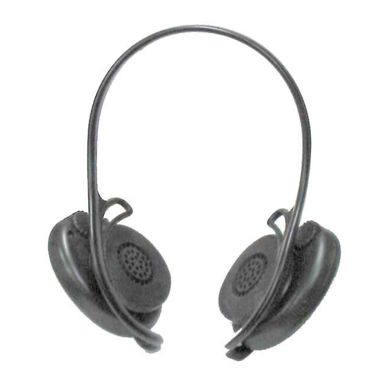
Sony SRF-H11 Service Manual
Fm stereo / am headphone radio
Hide thumbs
Also See for SRF-H11:
- Operating instructions (2 pages) ,
- Operating instructions (2 pages) ,
- Specifications (2 pages)
Table of Contents
Advertisement
Quick Links
SERVICE MANUAL
Ver 1.0 2003.04
Sony Corporation
9-877-300-01
2003D0200-1
Personal Audio Company
Published by Sony Engineering Corporation
C 2003.04
SPECIFICATIONS
Frequency range
FM:87.5 – 108 MHz
AM:530 – 1 710 kHz
Power output
6 mW + 6 mW (at 10% harmonic distortion)
Headphone type
Dynamic
Power requirements
1.5 V DC, one R03 (size AAA) battery
Mass Approx. 115 g (4 oz) incl. a battery
Design and specifications are subject to change without notice.
FM STEREO / AM HEADPHONE RADIO
SRF-H11
French Model
Advertisement
Table of Contents

Summary of Contents for Sony SRF-H11
-
Page 1: Specifications
1.5 V DC, one R03 (size AAA) battery Mass Approx. 115 g (4 oz) incl. a battery Design and specifications are subject to change without notice. FM STEREO / AM HEADPHONE RADIO Sony Corporation 9-877-300-01 2003D0200-1 Personal Audio Company Published by Sony Engineering Corporation C 2003.04... -
Page 2: Table Of Contents
SRF-H11 TABLE OF CONTENTS • UNLEADED SOLDER Boards requiring use of unleaded solder are printed with the Specifications ................1 lead-free mark (LF) indicating the solder contains no lead. (Caution: Some printed circuit boards may not come printed SERVICING NOTE ........... -
Page 3: Servicing Note
SECTION 1 SERVICING NOTE DRIP-PROOF TREATMENT Be sure to execute the following, when the cabinet is removed during service. Apply the SONY coating sealant TSE392-W (7-432-950-03) to the hatched portion shown in figure using an applicator, etc. Knob Poly-slider washer TSE392-W... -
Page 4: General
SRF-H11 SECTION 2 This section is extracted from instruction manual. GENERAL Location and function of controls BAND TUNE FM DX/LOCAL•AM R03 (size AAA) x 1 Driver units Battery compartment Neck band/Bandeau/ Light reflector (R, L) This reflector reflects car lights at night for your safety. -
Page 5: Disassembly
SRF-H11 SECTION 3 DISASSEMBLY The equipment can be removed using the following procedure. Belt DRIVER (Headphone) (R) Main board DRIVER (Headphone) (L) Audio board Note : Follow the disassembly procedure in the numerical order given. 3-1. BELT REMOVAL Belt 1 Claws... -
Page 6: Main Board Removal
SRF-H11 3-4. MAIN BOARD REMOVAL Main board 2 Claw 1 Three screws (+BVTT1.7 x 8) Cabinet (front) R 4 Remve solder 2 Claw Cabinet (rear) R 3-5. AUDIO BOARD REMOVAL Lid, Audio board battery case 3 Screw (+BVTT1.7 x 8) -
Page 7: Gear (Tuning Capacitor) Installation
SRF-H11 SECTION 4 Gear (tuning capacitor) installation Note : Follow the installation procedure in the numerical order given. 1 Turn the PVC shaft all the way counterclockwise. 2 Set the gear (VC) onto the PVC shaft and secure it with screw. -
Page 8: Electrical Adjustments
SRF-H11 SECTION 5 ELECTRICAL ADJUSTMENTS • Repeat the procedures in each adjustment several times, and the TUNER SECTION 0 dB=1µ V frequency coverage and tracking adjustments should be finally • POWER switch : ON done by the trimmer capacitors. • VOL... - Page 9 SRF-H11 FM 2nd OSC Adjustment FM VCO Adjustment Procedure : Procedure : 1. Turn the set to optional frequency. FM RF signal 2. Connect an electrolytic capacitor (10µF/16V) between pin !¡ generator WIRE ANTENNA of IC1 and ground. input 3. Connect the frequency counter to @¢ pin and GND of IC1 as 0.01µF...
- Page 10 SRF-H11 Adjustment Location : L7 : AM Tracking Adjustment (SIDE A) MAIN BOARD CT1-1 : FM Frequency Coverage Adjustment CT1-2 : FM Tracking Adjustment CT1-4 : AM Tracking Adjustment CT1-3 : AM Frequency Coverage Adjustment FM wire antenna input (SIDE B)
-
Page 11: Diagrams
SRF-H11 SECTION 6 DIAGRAMS 6-1. PRINTED WIRING BOARDS Refer to page 12 for Notes. : Uses unleaded solder. (SIDE A) MAIN BOARD FERRITE-BAR ANTENNA (SIDE B) AUDIO BOARD 1-686-469- (12) 1-686-470- (12) BAND FM LOCAL FM DX WIRE ANTENNA (SIDE A) -
Page 12: Schematic Diagram
SRF-H11 6-2. SCHEMATIC DIAGRAM Note on Schematic Diagram: • All capacitors are in µF unless otherwise noted. pF: µµF 50 WV or less are not indicated except for electrolytics and tantalums. • All resistors are in Ω and W or less unless otherwise specified. -
Page 13: Ic Block Diagrams
SRF-H11 IC BLOCK DIAGRAMS IC1 CXA1129N-T4 30 29 24 23 FM/TV 38KHz FM/AM R CH OVER LOAD LOCAL FM/TV L CH LEVEL SELECT CONTROL FM/TV FM/TV RF AMP π/2 COUNTER DISCRI BUFF LOAD CONTROL SELECT FM/TV LIMITTER 38KHz MUTE AM IF AMP... -
Page 14: Exploded View
SRF-H11 SECTION 7 EXPLODED VIEWS NOTE : • -XX, -X mean standardized parts, so they • The mechanical parts with no reference may have some difference from the original number in the exploded views are not one. supplied. • Items marked “ * ”are not stocked since they •... -
Page 15: Electrical Parts List
SRF-H11 SECTION 8 AUDIO MAIN ELECTRICAL PARTS LIST Ref. No. NOTE: Part No. Description Remarks • Due to standardization, replacements in the • Items marked “*” are not stocked since they When indicating parts by reference parts list may be different from the parts speci- are seldom required for routine service. - Page 16 SRF-H11 MAIN Ref. No. Part No. Description Remarks Ref. No. Part No. Description Remarks 1-162-915-11 CERAMIC CHIP 10PF 0.5PF < VARIABLE CAPACITOR > CT1-1 1-141-524-12 CAP, VAR (FM FREQUENCY COVEREGE) CT1-2 1-141-524-12 CAP, VAR (FM TRACKING) CT1-3 1-141-524-12 CAP, VAR (AM FREQUENCY COVEREGE)
- Page 17 SRF-H11 MEMO...
-
Page 18: Revision History
SRF-H11 REVISION HISTORY Clicking the version allows you to jump to the revised page. Also, clicking the version at the upper right on the revised page allows you to jump to the next revised page. Ver. Date Description of Revision...


