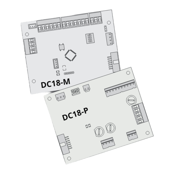
Summary of Contents for tau DC18
- Page 1 INSTALLATION GUIDE GUIDA ALL’INSTALLAZIONE NOTICE D’INSTALLATION DC18 IT - Istruzioni originali...
- Page 2 DC18 WIRING DIAGRAM WITH ACTIVATION AND SAFETY SENSORS SENSOR CLOSED SIDE SENSOR OPEN SIDE SENSOR CLOSED SIDE SENSOR OPEN SIDE DOORSS340/1023T DOORSS340/1023T DOORRADMU DOORRADM START EMERGENCY ENCODER DL 1 LED3 LED2 DC18-M...
- Page 3 * su richiesta SEZIONATORE MOTORE SERR.ELET. BATTERIA ALIMENTAZIONE DI RETE 115 Vac +/-10%, 60Hz SCHEDA CARICA BATTERIE 230V ac DC18-P 3,15 A NEUTRO TERRA 6,3 A FASE SECONDARIO TF PRIMARIO TF...
- Page 4 DC18 WIRING DIAGRAM WITH ACTIVATION AND SAFETY SENSORS DOORRAD2 AND DOORSS340/1023T OUTSIDE SENSOR SENSOR CLOSED SIDE SENSOR OPEN SIDE S-10DOORRAD2 DOORSS340/1023T DOORSS340/1023T TEST POWER START EMERGENCY ENCODER DL 1 LED3 LED2 DC18-M...
- Page 5 OUTSIDE SENSOR S-10DOORRAD2 TEST POWER SEZIONATORE MOTORE SERR.ELET. BATTERIA ALIMENTAZIONE DI RETE SCHEDA CARICA BATTERIE 230V ac DC18-P * su richiesta 115 Vac 3,15 A +/-10%, 60Hz NEUTRO TERRA 6,3 A FASE SECONDARIO TF PRIMARIO TF...
-
Page 6: Installation
Important information: Disconnect the panel from the power supply before opening it. The DC18 control unit has been designed to control an electromechanical gear motor for auto- mating gates and doors of all kinds. Any other use is considered improper and is consequently forbidden by current laws. - Page 7 1. ELECTRIC ARRANGEMENTS NOTE: The grey part indicates the survey zone of radar and sensors. The number of cables and the relevant section in mm is indicated for every device. 1) EXTERNAL RADAR (4x0,5mm) 2) INTERNAL RADAR (4x0,5mm) 3) OPENING CONTROL (2x0,5mm) 4) PROGRAM SELECTOR (4x0,5mm) 5) SAFETY SENSOR FOR CLOSING (6x0,5mm) 6) SAFETY SENSOR FOR OPENING(6x0,5mm)
-
Page 8: Technical Characteristics
CONTROL PANEL FOR AUTOMATIC SWING DOOR • MICROPROCESSOR-BASED CONTROLLER • ENCODER SENSOR FOR SELF-LEARNING OF TRAVEL • CONNECTOR FOR BATTERY • DIAGNOSTICS LEDS ATTENTION: do not use single cables (with one single wire), ex. telephone cables, in order to avoid breakdowns of the line and false contacts;... - Page 9 Inside Radar “SOLO USCITA” Exiting Traffic Start / PP (EXIT ONLY) Emergency “SEMPRE CHIUSA” Door always closed Emergency (time to exit 10 sec.) (HOLD CLOSE) To move the door “MANUAL” manually without controlling the motor “SEMPRE APERTA” Door remains always (HOLD OPEN) open Outside Radar...
- Page 10 CONNETTORE J13 - sensor connection: Terminals Function Description INTERNAL SENSOR Opens in “EXIT ONLY” and “AUTO”. 11 - 12 (N.O. contact) Door won’t close until sensor is released. EXTERNAL SENSOR Opens in “ENTANCE ONLY” and “AUTO”. 11 - 13 (N.O. contact) Door won’t close until sensor is released.
- Page 11 SHOLD OPEN = Keeps door fully open. AUTO = All Opening Inputs enabled EXIT ONLY = Disables Outside Radar. MANUAL = To move the door manually with- 0419 out controlling the motor. LOCK = Keeps door closed, allowing opening only with EMERGENCY Input (with Dip #1 on SW1 on ON).
- Page 12 SENSOR TEST SETTING • Use only sensors which feature testing wires, connecting these to the wire terminals 8 and 10 of the controller DC18; • Set DIP #15 and #16 on to ON in order to enable the test; •...
- Page 13 DIAGNOSTICS LEDs AND BUZZER DIAGNOSTIC POWER SUPPLY 12 V POWER SUPPLY 5 V AUX POWER SUPPLY 24 V DC Red LED for signaling MOTOR POWER SUPPLY 40V DC DL1 LED ERRORS Key: LED steady on; LED flashing; Automation warnings: automation closed – everything OK; green - flashing every 4 seconds automation moving (opening/closing);...
-
Page 14: Troubleshooting
TROUBLESHOOTING MALFUNCTION POSSIBLE CAUSE ACTION DL1 flashes green/ Perform LEARNING as described in LEARNING Missing. red alternately. LEARNING section. Safety or Command Inputs are not correctly connect- Check connections on wire terminals. During LEARNING motor won’t move. Safety or Command Inputs Remove obstacle from Sensor or Photo- are in use. - Page 15 In the case of a swing door with two overlapping closing leaves and installed on emergency exits, the installer must measure the force required to open both leaves of the door by manually pushing the Slave leaf in the direction of escape (most un- favorable).
- Page 16 DC18-M MASTER DC18-M SLAVE...
- Page 20 Via Enrico Fermi, 43 - 36066 Sandrigo (VI) - Italy Tel +39 0444 750190 - Fax +39 0444 750376 info@tauitalia.com - www.tauitalia.com Foglietto illustrativo CARTA - Raccolta differenziata. Segui le indicazioni del tuo comune. (N.B.: togliere i punti metallici) Instruction leaflet PAPER - Waste separation.


