Advertisement
Quick Links
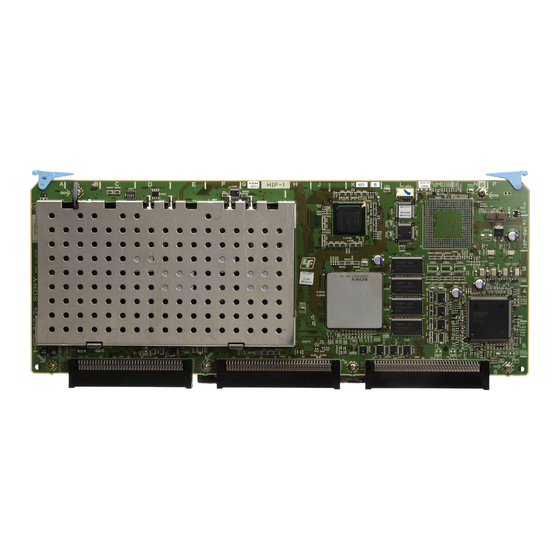
HD UPCONVERTER BOARD
BKMW-104
! WARNING
This manual is intended for qualified service personnel only.
To reduce the risk of electric shock, fire or injury, do not perform any servicing other than that
contained in the operating instructions unless you are qualified to do so. Refer all servicing to
qualified service personnel.
! WARNUNG
Die Anleitung ist nur für qualifiziertes Fachpersonal bestimmt.
Alle Wartungsarbeiten dürfen nur von qualifiziertem Fachpersonal ausgeführt werden. Um die
Gefahr eines elektrischen Schlages, Feuergefahr und Verletzungen zu vermeiden, sind bei
Wartungsarbeiten strikt die Angaben in der Anleitung zu befolgen. Andere als die angegeben
Wartungsarbeiten dürfen nur von Personen ausgeführt werden, die eine spezielle Befähigung
dazu besitzen.
! AVERTISSEMENT
Ce manual est destiné uniquement aux personnes compétentes en charge de l'entretien. Afin
de réduire les risques de décharge électrique, d'incendie ou de blessure n'effectuer que les
réparations indiquées dans le mode d'emploi à moins d'être qualifié pour en effectuer d'autres.
Pour toute réparation faire appel à une personne compétente uniquement.
INSTALLATION MANUAL
1st Edition (Revised 3)
Advertisement

Summary of Contents for Sony BKMW-104
- Page 1 HD UPCONVERTER BOARD BKMW-104 ! WARNING This manual is intended for qualified service personnel only. To reduce the risk of electric shock, fire or injury, do not perform any servicing other than that contained in the operating instructions unless you are qualified to do so. Refer all servicing to qualified service personnel.
- Page 3 1-1 (J) BKMW-104...
- Page 4 1-2 (J) BKMW-104...
- Page 5 1-3 (J) BKMW-104...
- Page 6 1-4 (J) BKMW-104...
- Page 7 1-5 (J) BKMW-104...
-
Page 9: Section 1 Installation
Output connectors HD SDI OUTPUT connectors panel of the VTR. Be sure to attach the BKMW-104 in accordance with Section 1-3. . This unit cannot be used together with Network Interface Board BKMW-E2000/E3000. . When this unit is installed onto MSW-M2000E/... - Page 10 SDI and HD SDI: BNC 75 Z, MALE For the detailed information for each menu of the mainte- (Sony part No.: 1-569-370-12) nance mode, refer to Section 3 of the maintenance manual volume-1 of the VTR. . SDI connection cable: Max.
-
Page 11: Installation Procedures
When the SY ROM version is lower than above, the the HIF-1B assembly. VTR will not operate properly even if the BKMW-104 is correctly installed. When updating the software is HIF-1B assembly required, contact your local Sony Sales Office/Service Center. - Page 12 1-3. Installation Procedures 7. Route the coaxial cables of the BKMW-104’s SDI/HD For the player SDI panel assembly through the hole of the VTR (1) Affix the blank panel of the supplied accessories chassis. onto the SDI/HD SDI panel assembly.
- Page 13 11. Reattach the upper lid (rear) assembly of the VTR, and tighten the two screws (with stopper). 12. Affix a VIDEO CONTROL label of the supplied accessory above the OPTION connector (D-SUB 9 pin) on the connector panel of the VTR. VIDEO CONTROL label 1-5 (E) BKMW-104...
- Page 15 The material contained in this manual consists of information that is the property of Sony Corporation. Sony Corporation expressly prohibits the duplication of any portion of this manual or the use thereof for any purpose other than the operation or maintenance of the equipment described in this manual without the express written permission of Sony Corporation.
- Page 16 Printed in Japan Sony Corporation BKMW-104 (SY) J, E 2004. 8 08 B&P Company 3-206-744-04 ©2002...


