Sign In
Upload
Manuals
Brands
Toshiba Manuals
All in One Printer
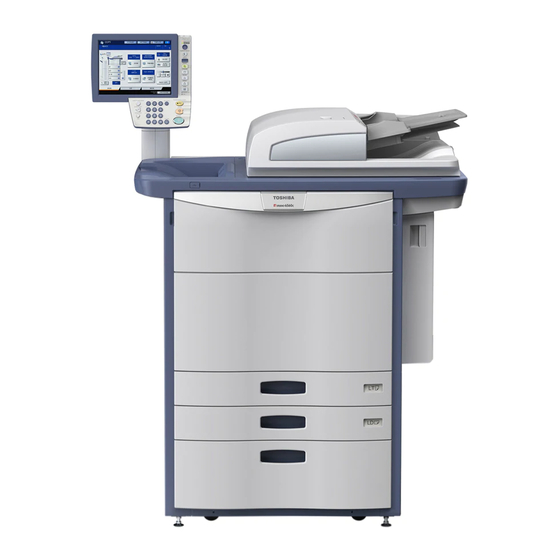
E-Studio 5540c
Toshiba E-Studio 5540c Manuals
Manuals and User Guides for Toshiba E-Studio 5540c. We have
3
Toshiba E-Studio 5540c manuals available for free PDF download: Service Manual, Troubleshooting Manual, Manual
Toshiba E-Studio 5540c Service Manual (1500 pages)
MULTIFUNCTIONAL DIGITAL COLOR SYSTEMS
Brand:
Toshiba
| Category:
All in One Printer
| Size: 96.4 MB
Table of Contents
Service Manual
1
Cautionary Labels
5
Precautions for Transporting Equipment Once Unpacked
7
General Description
7
Precautions and Procedures for Transporting Equipment
8
Checking Gaskets in the RADF
8
Fixing the Scanning Section
8
Installing a Drum Protection Sheet
10
Installing the Sealing Material in Toner Supply Opening
11
Contents
17
Main Feature of E-STUDIO5540C/6540C/6550C
33
Main Feature of E-STUDIO5560C/6560C/6570C
33
Specifications
35
General
35
Copy Specifications
38
First Copy Time
38
Copy Speed
39
System Copy Speed
42
Print
43
Scan
43
E-Filing
43
Network Fax
44
Internet FAX Transmission
44
Internet FAX Receiving
44
Accessories
45
System List (E-STUDIO5540C/6540C/6550C)
46
System List (E-STUDIO5560C/6560C/6570C)
47
Supplies
48
Outline of the Machine
49
Sectional View
49
Front Side
49
Rear Side
51
Electric Parts Layout
52
Reversing Automatic Document Feeder (RADF)
52
Scanner Unit
54
Bridge Unit/Paper Exit
55
Fuser Related Section
56
Developer Unit
58
Transfer Belt Unit
61
Transfer Unit
62
Laser Unit
63
Toner Cartridge/Waste Toner Box
64
Automatic Duplexing Unit
65
Cover Switches/Cover Sensor/Tru Waste Toner Box
66
Bypass Feed Unit
67
Paper Feeding Section
68
Tandem LCF
70
PC Boards
71
Power Supply
72
Fans
73
Damp Heater
74
Control Panel
75
Symbols and Functions of Various Components
76
Motors
76
Sensors
79
Switches
84
Electromagnetic Spring Clutches
84
Solenoids
85
Lamps, Coils, and Heaters
87
Thermistors, Thermopiles, and Thermostats
87
Transformer
88
Others
88
Copy Process
89
Comparison with E-STUDIO5520C/6520C/6530C
90
Comparison with E-STUDIO5540C/6540C/6550C
92
General Operation
94
Overview of Operation
94
Description of Operation
95
Warming-Up
95
Ready
96
Drawer Feed Copying
96
Bypass Feed Copying
99
Interruption Copying
99
Detection of Abnormality
100
Types of Abnormality
100
Description of Abnormality
100
Add Paper
100
Paper Misfeed in Bypass
102
No Toner in the Cartridge
102
Misfeed in Equipment
103
Waste Toner Box Replacement
104
Call for Service
104
Hibernation Function
105
Control Panel: E-STUDIO5540C/6540C/6550C
106
Control Panel: E-STUDIO5560C/6560C/6570C
107
Dot Matrix LCD Circuit
108
Structure
108
Scanner
109
Construction
110
Functions
111
CCD Driving PC Board
111
Scanning Section Control PC Board
111
Automatic Original Detection Sensor
111
Scanning Operation
112
Principle of Original Size Detection
113
Sensor Detection Points
113
Laser Optical Unit
114
Laser Precautions
115
Slit Glass Cleaning Mechanism
116
Paper Feeding System
117
Tandem LCF Model
118
Composition
119
Drive of Rollers
122
Operation of Bypass Pickup Roller
123
Operation of Drawer Pickup Roller
124
Paper Size Detection
125
From Power-ON to Ready Status
126
Ready Status
126
Bypass Feeding
126
Drawer Feeding
127
Process Unit Related Section
128
Electric Circuit Description
135
Drum Surface Potential Sensor Control Circuit
135
Configuration
135
Self Steering Mechanism
138
Operation Flow
138
Image Quality Control
139
Fuser Unit
140
Difference of Fuser Units
142
Difference for Destination of Fuser Unit
143
Heat Pipe Roller
144
Fuser Unit Control Circuit
145
Temperature Detection Section
148
Fuser Unit Error Status Counter Control
148
Temperature Detection Circuit
148
Abnormality Detection by the Thermistors and Thermopiles
149
Exit / Reverse / Duplex Section
154
Bridge Unit
155
Duplexing Bridge Unit / Duplexing Unit
156
Description of Operations
158
Paper Transport Paths
159
Upper Exit Section
159
Lower Exit Section
160
Drive
163
Original Size Detection
164
Outline
164
Original Tray Width Sensor
164
Original Width Detection Sensors-1,-2,-3/Original Registration Sensor
164
A4 Series (Width Sizes Mixed at A3 / A4 Standard)
165
A4 Series (Width Sizes Mixed at B4 / B5 Standard)
165
A4 Series (Width Sizes Mixed at A4-R Standard)
165
A4 Series (Width Sizes Mixed at B5-R Standard)
165
LT Series (Width Sizes Mixed at LD / LT Standard)
166
LT Series (Width Sizes Mixed at COMP Standard)
166
LT Series (Width Sizes Mixed at LG / LT-R Standard)
166
Power Supply Unit
167
Operation of DC Output Circuits
168
Output Channel
170
Output Voltage by the Type of Connector
171
Main Power Switch Line
171
Cover Switch Line
171
AC Line
171
Fuse
172
Disassembly and Replacement of Covers
175
Front Lower Cover
175
Front Cover
175
Top Right Cover
176
Right Top Cover
176
Top Front Cover
176
Top Left Cover
177
FAX Cover
177
Receiving Tray
177
Left Middle Cover
178
Left Top Cover
178
Left Lower Cover
178
Bypass Tray Unit (Removing Tray Arm)
179
Duplexing Unit Front Cover
179
Duplexing Unit Rear Cover
179
Paper Feed Cover
180
RADF Connector Cover
180
Right Rear Cover
180
Upper Exhaust Fan Cover
181
Top Rear Cover
181
Left Corner Cover
182
Right Corner Cover
182
Control Panel Unit
183
Control Panel Rear Cover
184
Display PC Board
184
Shielding Plate
185
Key PC Board-1
187
Key PC Board-2
187
Touch Panel
187
Control Panel Cover
188
Original Glass
189
Lens Cover
190
SLG Board Cooling Fan
190
Automatic Original Detection Sensor
191
A4 Series (APS-1, -2, -3, -C, -R)
191
LT Series (APS-2, -3, -C, -R)
191
Exposure Lamp
192
Exposure Lamp Cooling Fan-1
194
Scanner Unit Cooling Fan-1
195
Exposure Lamp Cooling Fan-2
196
Upper Exhaust Fan (Left)
197
Upper Exhaust Fan (Right)
199
Lens Unit
200
Scan Motor
201
Installation of Lens Unit
201
Carriage-1
202
Inverter Board
204
Carriage Wire / Carriage-2
204
Installing Carriage Wires
206
Winding the Wires Around the Wire Pulley
207
Carriage Home Position Sensor (S6)
208
Platen Sensor (S7)
208
SLG Board (SLG)
208
Laser Optical Unit Cooling Fan (Front)
212
Laser Optical Unit Cooling Fan (Rear)
214
Shutter Motor
215
Shutter Sensor (Home Position)
216
Shutter Sensor (End Position)
217
Disassembly and Replacement of the Polygonal Motor
217
Bypass Feed Tray
219
Bypass Pickup Solenoid
220
Bypass Paper Sensor
220
Bypass Pickup Roller
221
Bypass Upper Unit
222
Bypass Feed Roller
223
Bypass Transport Roller
223
Bypass Motor
224
1St Drawer Idling Roller
225
Bypass Separation Roller
226
Bypass Feed Sensor
228
Bypass Paper Size Detection Sensor
228
Drawer Feeding Unit
229
Feed Roller
230
Pickup Roller
230
Separation Roller
231
Transport Roller
231
Drawer Detection Sensor
233
Drawer Feed Sensor
234
Drawer Transport Sensor
234
Drawer Empty Sensor
235
Drawer Tray-Up Sensor
235
Drawer Bottom Sensor
236
Registration Roller
236
Paper Dust Cleaning Brush (Registration Roller)
237
Registration Guide
237
Registration Sensor
238
Registration Roller (Metal)
239
2Nd Transfer Side Paper Clinging Detection Sensor
239
Media Sensor
240
Feed Cover Sensor
242
Drawer
242
Drawer Paper Size Detection Sensor-1/2
243
Registration Motor
243
Feed/Transport Drive Unit
244
Transport Motor-1
244
Transport Motor-2
245
Feed Motor
245
Feed/Transport Motor
245
Paper Feed Drive Unit
246
3Rd Drawer Transport Clutch/3Rd Drawer Feed Clutch
246
4Th Drawer Transport Clutch/4Th Drawer Feed Clutch
248
Tray-Up Motor-1
249
Tray-Up Motor-2
251
Transfer Belt Paper Clinging Detection Sensor
252
Tandem LCF Tray-Up Motor
253
Tandem LCF End Fence Motor
254
Tandem LCF Standby Unit
255
Tandem LCF Feeding Unit
256
Stopper Opening/Closing Solenoid
256
Stopper Opening/Closing Detection Sensor
256
Tandem LCF Bottom Sensor
259
Standby Side Tray Paper Amount Detection Sensor
259
End Fence Home Position Sensor
261
End Fence Stop Position Sensor
262
Standby Side Empty Sensor
263
Standby Side Tray Detection Sensor
263
Tandem LCF Solenoid
264
Pulling out the Process Unit
265
Drum Cleaner Unit
269
Drum Cleaning Blade
271
Blade Side Seal
272
Main Charger Unit
273
Main Charger Grid
273
Needle Electrode Cleaner
273
Needle Electrode
274
Discharge LED
274
Sub-Hopper
274
Sub-Hopper Toner Sensor
275
EPU Cover
275
Sub-Hopper Toner Motor
276
EPU PC Board
277
Drum Surface Potential Sensors Control PC Board
278
Auger Lock Detection Sensor
278
Main Charger Ozone Exhaust Fan-K/-C/-M/-Y
279
Needle Electrode Cleaner Detection Sensor-K/C/M/Y
280
Needle Electrode Cleaner Motor-K/-C/-M/-Y
280
V0 Sensor Shutter Solenoid (K) (SOL)
281
Drum Surface Potential Sensor (K) (S34)
283
Drum Thermistor (K/Y)
284
Developer Unit
284
Developer Material
286
Developer Sleeve
288
Doctor Blade
290
Auto-Toner Sensor-K/C/M/Y
290
Drum Drive Unit
291
Drum Motor-K
292
Drum Motor-YMC
292
K Drum Phase Sensor
293
Color Drum Phase Sensor
294
Developer Unit Motor-K/YMC
295
Developer Unit Mixer Motor-K/YMC
295
Developer Drive Unit
295
Waste Toner Box
296
Waste Toner Amount Detection Sensor
297
Waste Toner Box Full Detection Sensor
298
Waste Toner Box Detection Sensor
299
Ozone Filter-1
299
Ozone Filter-2
300
Toner Filter
300
Toner Motor (K/C/M/Y)
302
Toner Cartridge Paddle Rotation Detection Sensor-K/C/M/Y
304
Waste Toner Transport Motor
304
Waste Toner Transport Unit
305
Ozone Suctioning Fan
306
Toner Cartridge Heat Insulation Fan
307
Toner Cooling Exhaust Fan
308
Temperature/Humidity Sensor
309
Toner Motor Interlock Switch
309
EPU Cooling Fan
311
Scattered Toner Suctioning Fan
311
Pulling out the Transfer Belt Unit
313
2Nd Transfer Facing Roller Cleaning Pad
315
Transfer Belt Cleaning Unit
315
Transfer Belt Cleaning Blade
317
Transfer Belt Cleaner Side Seal
317
Transfer Belt Unit (TBU)
318
Transfer Belt
320
Transfer Belt Cam Motor
322
Transfer Belt Contact/Release Detection Sensor
322
1St Transfer Roller
323
Cleanable Facing Roller
323
Tension Roller
325
2Nd Transfer Facing Roller
325
2Nd Transfer Unit (TRU)
328
2Nd Transfer Roller
330
2Nd Transfer Roller Lubricant Unit
330
2Nd Transfer Roller Cleaning Blade
331
2Nd Transfer Roller Side Seal
331
TRU Waste Toner Box
333
TRU Waste Toner Amount Detection Sensor
333
TRU Waste Toner Auger Drive Section
334
TRU Waste Toner Transport Motor
335
TRU Waste Toner Motor
336
Transfer Belt Motor
336
2Nd Transfer Roller Contact/Release Detection Sensor
337
2Nd Transfer Cam Motor
338
2Nd Transfer Cam Drive Unit
338
Image Quality Control Unit
339
Image Position Aligning Sensor (Front)
339
Image Position Aligning Sensor (Center)
339
Image Position Aligning Sensor (Rear)
340
Image Quality Sensor
340
Image Quality Shutter Solenoid
341
Pressure Roller Cover
347
Transport Guide-1
348
Transport Guide-2
348
Entrance Guide Cover
349
Separation Finger
349
Separation Plate
350
Pressure Roller/Pressure Roller Heater Lamp (LAMP)
352
Fuser Belt/ Fuser Roller/ Fuser Belt Guide/ Heat Pipe Roller
356
Fuser Belt Rotation Detection Sensor
362
Fuser Belt Thermostat
363
Fuser Belt Edge Thermistor
364
Pressure Roller Center Thermistor/ Pressure Roller Side Thermistor
366
Pressure Roller Edge Thermistor
366
Pressure Roller Contact/Release Sensor
368
Pressure Roller Center Thermostat/ Pressure Roller Side Thermostat
369
IH Coil
371
Fuser Belt Thermopile
373
Fuser Motor
373
Pressure Roller Contact/Release Clutch
374
Exit Paper Cooling Fan (Rear)
376
IH Cooling Fan-1 / IH Cooling Fan-2
377
IH Board
378
Fuser Unit Jam Releasing LED
378
VOC Filter 1
379
VOC Filter 2
379
Upper Exit Section Cooling Fan-1/2
380
Lower Exit Section Cooling Fan-1/2
380
Lower Exit Section Cooling Fan-3
381
Exit Motor
381
Upper Paper Exit Sensor/Upper Exit Tray Paper Full Detection Sensor
382
Lower Paper Exit Sensor
383
Reverse Section Stationary Jam Detection Sensor
384
Reverse Path Cover Switch
385
Upper Paper Exit Roller
386
Lower Paper Exit Roller
387
Bridge Unit Front Cover
388
Bridge Unit Lower Cover
389
Bridge Unit Transport Entrance Motor/ Reverse Motor
390
Bridge Unit Transport Exit Motor
391
Bridge Unit Upper Cover
393
Bridge Unit Transport Roller-1
394
Bridge Unit Transport Roller-2
396
Bridge Unit Transport Roller-3
397
Reverse Roller
399
Bridge Unit Exit Roller-1
399
Bridge Unit Exit Roller-2
401
Transport Path Switching Solenoid-1
401
Transport Path Switching Solenoid-2
402
Bridge Unit Path Entrance Sensor
403
Bridge Unit Path Exit Sensor
404
Reverse Sensor
405
Exit Paper Cooling Fan (Front)
407
Bridge Unit Cooling Fan (Front)
409
Bridge Unit Cooling Fan (Rear)
410
Front Cover Opening/Closing Detection Switch
411
Bridge Unit Connecting Detection Switch
411
Duplexing Bridge Unit
412
Duplexing Unit Opening/Closing Detection Sensor
412
Reverse Path Sensor
413
Duplexing Bridge Unit Transport Roller
414
Duplexing Unit Upper Cover
415
Duplexing Unit Front Side Cover
416
Duplexing Unit Rear Side Cover
416
Reversed Paper Cooling Fan
416
ADU Motor-1
417
ADU Motor-2
418
ADU Board
419
ADU Transport Roller-1
419
ADU Transport Roller-2
421
ADU Transport Roller-3
423
Duplexing Unit Path Exit Sensor
423
Fuser Transport Sensor
424
Duplexing Unit Path Entrance Sensor
425
Duplexing Unit Cover Opening/Closing Detection Switch
426
Duplexing Unit Interlock Switch
427
Interlock Switch
428
Reversing Automatic Document Feeder
430
Radf
430
RADF Front Cover
431
RADF Rear Cover
432
Original Jam Access Cover
433
RADF Left Cover
434
Original Tray
434
Original Reverse Tray
435
Platen Sheet Unit
435
RADF Exit Tray
436
Reading Start Guide Unit
437
Exit Guide / Exit/Reverse Guide / Reading End Guide
438
Paper Feeder Unit
440
Original Registration Roller
444
Intermediate Transport Roller
445
Reading Start Roller
446
Reading End Roller
448
Exit Roller
449
Exit/Reverse Roller
450
Exit Intermediate Roller
451
Original Feed Motor (MR1)
454
Original Feed Motor Bracket
454
Read Motor
455
Read Motor Bracket
456
Original Reverse Motor
457
Original Exit Motor
457
RADF Cooling Fan
459
Original Pickup Solenoid
460
Original Reverse Solenoid
461
Original Exit Solenoid
462
Original Jam Access Cover Opening/Closing Switch
463
RADF Opening/Closing Switch
463
RADF Opening/Closing Sensor
465
Original Empty Sensor
465
Original Jam Access Cover Opening/Closing Sensor
466
Feeder Lower Guide Unit
466
Original Width Detection Sensor-3
467
Original Width Detection Sensor-2
467
Original Width Detection Sensor-1
468
Original Registration Sensor
468
Original Exit Sensor
468
Original Tray Sensor
469
Original Exit/Reverse Sensor
471
Original Reverse Unit Opening/Closing Sensor
472
Original Reading End Sensor
473
Original Intermediate Transport Sensor
473
Original Reading Start Sensor
473
RADF Board
475
RADF Board Bracket
475
Harness Guide
476
Removal and Installation of Options
477
MP-2501L/A (Large Capacity Feeder)
477
MJ-1103/1104 (Finisher)
479
MJ-6102 (Hole Punch Unit)
481
Self-Diagnistic Mode
485
Overview
485
Starting each Mode
485
Exiting from each Mode
485
State Transition Diagram of Self-Diagnosis Modes
486
About each Mode
486
Service UI
489
Login Procedure
489
In the Normal Mode
489
In the Security Mode
490
Service Mode Screen
491
Setting/Changing Password
491
Input Check (Test Mode 03)
492
Example of Display During Input Check
492
Output Check (Test Mode 03)
493
Test Print Mode (Test Mode 04)
494
Operation Procedure in Adjustment Mode (05)
495
Test Print Pattern in Adjustment Mode
497
Operation Procedure in Setting Mode
501
Assist Mode
503
Operating Procedure
505
HDD Assist Mode
506
Operation Procedure
506
Revert Factory Initial Status HDD
507
Remove Key
508
File System Recovery Mode
510
Check of the File System
511
Recovery of the File System
511
Initialize the File System
512
Initialize the DB
513
Displaying Various Data in the HDD
513
Displaying Usage Rate of each Partition
514
Initialization of Log File
514
SRAM Clear Mode
515
Set Serial Number
516
Clear SRAM
516
Reset Date and Time
516
SRAM Re-Initialize Support
516
List Print Mode
517
Print out
517
CSV Output
517
List Printing
518
Adjustment Mode
519
Setting Mode
520
PM Support Mode
521
Stored Information of Pixel Counter
522
Stored Information of Pixel Counter (Service Technician Reference)
523
Error History
524
Firmware Update Log
525
Power-ON/OFF Log
526
Version List
527
Engine Firmware Log
528
Total Counter List
529
Adjustment Value/Setting Value Difference
530
Pixel Counter
531
Factors Affecting Toner Consumption
531
Details of Pixel Counter
532
Type of Calculated Data
534
Relation between Pixel Count and Toner Consumption
535
Pixel Counter Confirmation
535
Reference Selection Screen
536
Information Screen of Toner Cartridge Reference
537
Information Screen of Service Technician Reference
537
Data List of Toner Cartridge Reference
539
Data List of Service Technician Reference
540
Pixel Count Code Table (Toner Cartridge Reference)
541
Pixel Count Code Table (Service Technician Reference)
541
Pixel Count Code Table
542
Default Setting / Restore Setting of the EFI Printer Board
544
Batch Setting for Self-Diagnostic Codes
545
Applicable Codes
545
Setting Files
545
Example
545
Result Files
546
Setting Adjustment
549
Image Related Adjustment
549
Adjustment Order
549
Adjustment of the Auto-Toner Sensor
550
Performing Image Quality Control
552
Adjustment of Color Registration Control
555
Image Dimensional Adjustment (General Description)
556
Procedure to Key in Adjustment Values
557
Paper Alignment at the Registration Roller
558
Adjustment with Touch Panel
558
Select the Drawer
558
Select the Paper Size
558
Adjustment by Direct Code Entry
561
Printer-Related Image Dimensional Adjustment
564
Reproduction Ratio of Primary Scanning Direction
565
Primary Scanning Data Laser Writing Start Position
566
Reproduction Ratio of Secondary Scanning Direction
567
Confirmation of 05-4526-0
567
Adjustment of 05-4526-0
567
Image Position of Secondary Scanning Direction
568
Primary Scanning Data Laser Writing Start Position at Duplexing
569
Adjustment for Long-Sized Paper
569
Adjustment for Short-Sized Paper
569
Adjustment for Medium-Sized Paper
570
Scanner-Related Image Dimensional Adjustment
571
Image Distortion
571
Reproduction Ratio Adjustment of Primary Scanning Direction
572
Image Location of Primary Scanning Direction
573
Image Location of Secondary Scanning Direction
573
Top Margin
574
Right Margin
575
Bottom Margin
576
Adjustments and Checks Using Test Chart No. TCC-1
577
Points to be Measured in the Chart
577
Checking Areas of the Chart and Their Descriptions
578
Image Quality Adjustment (Copying Function)
579
Automatic Gamma Adjustment
579
Density Adjustment
581
Color Balance Adjustment
582
Range of the Density Area
583
Gamma Balance Adjustment
584
Background Adjustment
585
Judgment Threshold for ACS
586
Sharpness Adjustment
586
Setting Range Correction
587
Adjustment of Smudged/Faint Text
587
Color Adjustment of Marker
588
Beam Level Conversion Setting
589
Maximum Toner Density Adjustment to Paper Type
590
Maximum Text Density Adjustment
590
Text/Photo Reproduction Level Adjustment
591
Black Header Density Level Adjustment
592
Black Area Adjustment in Twin Color Copy Mode
592
Judgment Threshold Adjustment for Blank Original
593
Background Offsetting Adjustment for RADF
593
Twin Color Copy / Mono Color Copy Adjustment
594
Maximum Density Adjustment for each Paper Type
595
ADF Noise Reduction
595
Image Quality Adjustment (Printing Function)
597
Gamma Balance Adjustment (Black Mode)
600
For Color Printing
603
Twin Color Print (600 Dpi)
604
Adjustment of Faint Text
606
Upper Limit Value at Toner Saving Mode
606
Maximum Toner Density Adjustment (OHP)
607
Fine Line Enhancement Switchover
608
“Pureblack/Puregray” Threshold Adjustment (PS)
608
“Pureblack/Puregray” Threshold Adjustment (PCL)
609
“Pureblack/Puregray” Threshold Adjustment (XPS)
609
“Pureblack/Puregray” Threshold Adjustment (Twin Color Print)
609
Toner Limit Threshold Adjustment
610
Screen Switchover
611
Adjustment of Smudged Text
614
Thin Line Width Lower Limit Adjustment
614
Color/Black Judgment Setting for Twin Color Printing Images
614
Density Adjustment of Graphic Lines
616
Image Quality Adjustment (Scanning Function)
618
Background Adjustment (Color Mode)
620
Judgment Threshold for ACS (Common for Copy and Scan)
620
Fine Adjustment of Black Density
622
RGB Conversion Method Selection
623
Adjustment of Saturation
623
Background Processing Offset Adjustment
624
Adjustment of the Capacity and Image Quality of Slimpdf
625
Surrounding Void Amount Adjustment
625
Scanning Function
626
Image Quality Adjustment (FAX Function)
627
Adjustment Carriages-1 and -2 Positions
629
Belt Tension Adjustment of the Scan Motor
630
Adjustment of the Media Sensor Position
631
Separation Roller Pressure Force Adjustment
632
Adjustment Procedure of the Drawer Feeding Unit
632
Adjustment Procedure of the Bypass Feed Unit
633
Sheet Sideways Deviation Caused by Paper Transporting Adjustment
636
Removal of the Drawer Paper Tray
636
Adjustment of the Gear Holder
637
Adjustment of the Rear Side Guide
637
In the Case of Bypass Feeding
638
Adjusting the Clearance of the Paper and Side Guides
639
High-Voltage Transformer Setting
640
Adjustment of the Doctor-Sleeve Gap
641
Adjustment of the Degree of the Transfer Belt Unit Parallelization
643
Gap Adjustment for Fuser Belt Thermostats
644
Gap to be Confirmed
645
Gap Confirmation Jig
645
Adjustment Procedure
646
Gap Adjustment for Pressure Roller Thermistors
648
Gap Adjustment for Pressure Roller Thermostats
651
Gap Adjustment for Separation Plate
654
RADF Position Adjustment
660
RADF Height Adjustment
665
Adjustment
665
RADF Image Skew Adjustment
667
Simplex Copying
667
Duplex Copying
668
RADF Leading Edge Position Adjustment
669
RADF Horizontal Position Adjustment
671
RADF Copy Ratio Adjustment
672
RADF Opening/Closing Switch Adjustment
673
Original Reading Start Sensor Adjustment
674
Automatic Adjustment
674
Manual Adjustment
674
Platen Sheet
677
Preventive Maintenance
679
PM Display
679
PM Display Conditions
679
PM Display Contents
680
Counter Clearing
681
General Descriptions for PM Procedure
682
Operational Flow
683
Operational Screen
684
Main Screen
684
Sub Screen (for Other than the Developer Unit)
685
Sub Screen (for the Developer Unit)
686
Sub Unit Detail Screen (for the Developer Material)
687
Clear Screen
688
Access Tree
689
Preventive Maintenance Checklist
693
Feed Unit
695
Duplexing Unit
697
Main Charger
699
Drum / Cleaner Unit / Filter
700
F1: Whole Cleaner Unit
701
F2: Drum
701
F3: Drum Cleaning Blade
702
F4: Blade Side Seal
702
F5: Recovery Blade
703
F7:Drum Surface Sensor/G8:Drum Surface Potential Sensor Shutter
703
F13: Toner Filter
703
Developer Unit (K, Y, M, and C)
704
G3: Developer Material
706
Transfer Belt Unit / Transfer Belt Cleaning Unit
708
I1: Transfer Belt
708
I2: 1St Transfer Roller
709
I3: Cleaning Facing Roller, I4: 2Nd Transfer Facing Roller
709
I6: Tension Roller, I7: Idling Roller
709
I8: Transfer Belt Cleaning Blade
709
L10: Transfer Belt Cleaner Side Seal
710
J1:Image Quality Sensor, J2:Sensor Shutter
711
J3:Image Position Aligning Sensor
711
2Nd Transfer Roller Unit
712
K1: 2Nd Transfer Roller
713
K3: 2Nd Transfer Roller Side Seal
713
K8: Grounding Plate
714
K9: Paper Dust Cleaning Brush (Registration Roller)
714
K12: TRU Waste Toner Auger Drive Gear
714
L1: Pressure Roller, M6: Fuser Belt
715
L2: Pressure Roller Separation Finger
716
L3, L4: Pressure Roller Thermistor
716
L11: Separation Plate
717
L13: Fuser Unit Gear
717
L14: Fuser Belt Thermopile
717
L15: Rotor
717
Paper Exit Unit
718
Lcf (Mp-2501)
720
P5: Brush Unit
721
P6: Paper Path Section
721
Symbols/Value Used in the Checklist
722
A1: Original Glass, A2: RADF Original Glass
723
B6: Drive Gear
725
D3: Separation Roller
727
E1: Main Charger Case
728
Storage of Supplies and Replacement Parts
751
Pm Kit
752
Maintenance Part List
753
Grease List
755
Operational Items in Overhauling
755
Machine Refreshing Checklist
756
Error Code and Troubleshooting
757
If a Problem Continues Even after Performing All Troubleshooting
757
Collection of Debug Logs with a USB Device
758
Traceability Label
760
Management No.
760
Applicable Units
760
Label Attachment Position
761
Error Code List
762
Jam
762
Service Call
772
Error in Internet FAX / Scanning Function
782
Internet FAX Related Error
782
RFC Related Error
782
Electronic Filing Related Error
783
Remote Scanning Related Error
784
E-Mail Related Error
784
File Sharing Related Error
785
E-Mail Reception Related Error
787
Printer Function Error
789
Topaccess Related Error/Communication Error with External Application
790
MFP Access Error
792
Maintenance Error
792
Network Error
793
Diagnosis and Prescription for each Error Code
798
Check Item
798
Paper Transport Jam
798
Paper Misfeeding
801
Paper Transport Jam
806
Other Paper Jam
822
Cover Open Jam
831
RADF Jam
834
Jam in Bridge Unit
842
Paper Jam in Finisher Section
844
Paper Jam in Saddle Stitcher Section
851
Paper Jam in Puncher Unit
854
Paper Feeding System Related Service Call
868
Scanning System Related Service Call
871
Fuser Unit Related Service Call
874
Communication Related Service Call
883
RADF Related Service Call
887
Circuit Related Service Call
889
Laser Optical Unit Related Service Call
894
Finisher Related Service Call
897
Image Control Related Service Call
913
Copy Process Related Service Call
930
Other Service Call
941
Other Errors
1037
Drum Surface Potential Sensor Control Related Troubleshooting
1037
Troubleshooting at Unpacking
1041
Equipment Operation Disabled after Installation of Option(S)
1044
Wireless LAN Connection Disabled
1044
Advertisement
Toshiba E-Studio 5540c Troubleshooting Manual (118 pages)
Multifunctional Digital Color Systems
Brand:
Toshiba
| Category:
All in One Printer
| Size: 12.63 MB
Table of Contents
Troubleshooting Guide
1
How to Read this Manual
3
Symbols in this Manual
3
Table of Contents
5
Chapter 1 TROUBLESHOOTING for the HARDWARE
10
When this Screen Is Displayed
10
Messages Displayed on the Touch Panel
12
Clearing a Paper Jam
16
Locating a Paper Jam
16
Clearing a Paper Jam
17
Paper Jam in the Reversing Automatic Document Feeder (Lower)
18
Paper Jam in the Reversing Automatic Document Feeder (Upper)
19
Paper Jam in the External Large Capacity Feeder (Optional)
20
Paper Jam in the Drawer Feeding Portion
22
Paper Jam in the Drawers
23
Paper Jam in the Drawer of the Tandem Large Capacity Feeder
23
Paper Jam in the Bypass Tray
24
Paper Jam in the Right Side of the Equipment
24
Transport Unit
24
Fuser Unit
25
Paper Jam in the Duplexing Unit
27
Paper Jam in the Finisher and the Hole Punch Unit (both Optional)
28
Paper Jam in the Saddle Stitch Unit (Optional)
31
Paper Jam in the Receiving Unit
35
Paper Jam in the Bridge Unit
37
Clearing Paper Jams Caused by a Wrong Paper Size Setting
38
Clearing Paper Jams Caused by a Wrong Paper Type Setting
43
Clearing a Staple Jam
47
Staple Jam in the Finisher
47
Staple Jam in the Saddle Stitch Unit
48
Replacing a Toner Cartridge
51
Replacing a "Near Empty" Toner Cartridge
54
Replacing the Waste Toner Box
57
Refilling with Staples
59
Refilling the Finisher Staples
59
Refilling the Saddle Stitch Unit Staples
60
Cleaning the Hole Punch Dust bin
63
Chapter 2 TROUBLESHOOTING for COPYING
65
Copying Problems
66
Chapter 3 Troubleshooting for Printing
69
Print Job Problems
70
Clearing Print Job Errors
70
Cannot Remember the Document Password for a Private Print Job
71
Printing a Document Including Many Graphics Takes Time
71
Printer Driver Problems
72
Cannot Print (Port Setting Problems)
72
Cannot Print (SNMP Community Name Problems)
72
Command Line Options Not Processed
72
Retrieval of Printer Configuration Failed
73
Cannot Change Settings on the [Device Settings] Tab
73
Network Connection Problems
74
Cannot Print with the Equipment (Network Connection Problems)
74
Cannot Print with SMB Print
74
Cannot Print Properly with Appletalk Print
74
Client Problems
75
Checking the Client Status
75
Hardware Problems
76
Print Jobs Not Output
76
Chapter 4 TROUBLESHOOTING for SCANNING
77
Scanning Problems
78
Cannot E-Mail My Scans
78
Cannot Find the Data Saved in the Shared Folder
78
Chapter 5 Troubleshooting for E-Filing
79
E-Filing Web Utility Problems
80
E-Filing Web Utility Terminates the Session
80
Numerous Sub Windows Repeatedly Appear
80
Displaying the Items in the Contents Frame Takes a Long Time
80
Error Messages
81
Chapter 6 TROUBLESHOOTING for NETWORK CONNECTIONS
84
Locating the Equipment in the Network
84
Cannot Locate the Equipment in the Network
84
Cannot Locate the Equipment with Local Discovery
85
Equipment Does Not Respond to Ping Command
86
LDAP Search and Authentication Problems
87
Network Shutdown Occurs or Touch Panel Disabled after LDAP Search
87
LDAP Authentication Takes a Long Time
87
Printing Problems (Network Related)
88
SMB Print and Point&Print in a Windows Operating System Environment
88
Raw TCP or LPR Print in a Windows Operating System Environment
88
IPP Print in a Windows Operating System Environment
89
Novell Print in a Netware Environment
89
Macintosh Environment
90
Unix/Linux Environment
90
Setup Needs to Copy Windows Nt Files
91
Client Software CD Now Required
91
Network Fax (N/W-Fax) Driver Problems
91
N/W-Fax Driver Installation Error Messages
91
Location Does Not Contain Information about Your Hardware
92
This Port Is Currently in Use
92
Problem with the Current Printer Setup
92
N/W-Fax Driver General Errors
92
Fax Transmission Cannot be Performed with a Cover Sheet
93
Client Software Authentication Problems
94
Cannot Log in Using Client Software
94
Toshiba E-Studio 5540c Manual (20 pages)
High Security Mode Management Guide
Brand:
Toshiba
| Category:
All in One Printer
| Size: 0.69 MB
Table of Contents
Preface
3
How to Read this Manual
3
Table of Contents
5
The High Security Mode
7
Precautions on Using the High Security Mode
8
Confirmation of the Mode
8
Operational Conditions
9
Temporary Password
12
Conditions When a Temporary Password Is Used
12
Operation by a User When a Temporary Password Is Used
12
Hold (Fax)
13
The Initial Values
15
Precautions on the Initial Values
16
Logging in
16
Initial Value List
17
Advertisement
Advertisement
Related Products
Toshiba E-STUDIO 555
Toshiba E-studio 556
Toshiba E-studio 556se
Toshiba e-studio 5560c
Toshiba E-Studio 557
Toshiba E-studio 5520c
Toshiba E-Studio 5506AC
Toshiba E-Studio 5508AC
Toshiba e-STUDIO 5500c
Toshiba E-STUDIO 5518A
Toshiba Categories
Laptop
Air Conditioner
TV
LCD TV
All in One Printer
More Toshiba Manuals
Login
Sign In
OR
Sign in with Facebook
Sign in with Google
Upload manual
Upload from disk
Upload from URL