Sign In
Upload
Manuals
Brands
Toshiba Manuals
All in One Printer
DP-6550
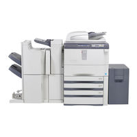
Toshiba DP-6550 Toner Cartridge Yellow Manuals
Manuals and User Guides for Toshiba DP-6550 Toner Cartridge Yellow. We have
1
Toshiba DP-6550 Toner Cartridge Yellow manual available for free PDF download: Service Manual
Toshiba DP-6550 Service Manual (404 pages)
MULTIFUNCTIONAL DIGITAL SYSTEMS
Brand:
Toshiba
| Category:
All in One Printer
| Size: 29.62 MB
Table of Contents
Service Manual
1
Table of Contents
11
1 Specifications/Accessories/Options/Supplies
17
Specifications
17
General
17
Copy
20
Print
29
Scan
29
E-Filing
29
Internet Fax
30
Network Fax
31
Accessories
32
Options
33
Supplies
34
System List
35
2 Outline of the Machine
37
Sectional View
37
Front View
37
Rear View
40
Electric Parts Layout
43
Symbols and Functions of Various Components
67
Motors
67
Sensors and Switches
69
Electromagnetic Spring Clutches
72
Solenoids
73
PC Boards
73
Lamps and Heaters
74
Thermistors and Thermostats
74
Transformer
75
Others
75
System Block Diagram
76
Installation and Replacement of Covers
77
Removal and Installation of Options
82
3 Copy Process
85
General Description
85
Details of Copy Process
86
Comparison of Copy Process to E-STUDIO550/650/810
95
4 General Operation
97
Overview of Operation
97
Description of Operation
97
Warming-Up
97
Ready State (Ready for Copying)
98
Drawer Feed Copying with the [START] Button
98
Bypass Feed Copying
102
Interruption Copying
102
Detection of Abnormality
103
Types of Abnormality
103
Description of Abnormality
103
5 Control Panel
107
General Description
107
Items Shown on the Display Panel
108
Display
108
Message
109
Relation between the Equipment State and Operator's Operation
114
Description of Operation
116
Dot Matrix LCD Circuit
116
LED Display Circuit
117
Disassembly and Replacement
118
6 Scanning Section
125
Function
125
Construction
126
Operation
127
Scanner Motor (M1)
127
Two-Phase Motor Drive Circuit (Fixed-Current Type)
128
Control for Exposure Lamp
129
General Description
129
Exposure Lamp
130
Control Circuit for Exposure Lamp
131
CCD Control
132
Opto-Electronic Conversion
132
Shading Correction
132
Automatic Original Size Detection Circuit
133
Principle of Original Size Detection
133
Process of Original Size Detection
133
Disassembly and Replacement
137
7 Laser Optical Unit
149
General Description
149
Structure
152
Laser Optical Unit
152
Polygonal Motor Unit
154
Fθ Lenses 1 and 2
156
H-Sync Detection PC Board (SNS Board)
156
Laser Driving Board (LDR1/LDR2 Board)
156
Slit Glass
156
Laser Diode Control Circuit
157
Polygonal Motor Control Circuit
158
Laser Unit Cooling Fan Control Circuit
159
Disassembly and Replacement
160
8 Paper Feeding System
163
General Description
163
Functions
165
Operation
167
Operation of Bypass Pickup Roller
167
Operation of Drawer Pickup Roller
167
Paper Separation
168
Driving
169
General Operation
170
Description of Tandem LCF Operation
171
Tray-Up Motor Control Circuit
174
Feed Motor Control Circuit
175
Transport Motor Control Circuit
176
Registration Motor Control Circuit
177
Tandem LCF Tray-Up Motor / End Fence Motor
178
Disassembly and Replacement
179
9 Process Related Section
203
Construction
203
Functions
204
Charger Wire Cleaner Control Circuit
205
General Description
205
Configuration
205
High-Voltage Transformer Control Circuit
206
General Description
206
Description of Operation
207
Drum Surface Potential Sensor Control Circuit
208
General Description
208
Configuration
208
Description of Operation
209
Temperature/Humidity Detection Circuit
210
Outline
210
Construction
210
Disassembly and Replacement
211
10 Drum/Cleaner Unit
219
Construction
219
Functions
220
Drum Temperature Detection Circuit
221
Image Quality Control
222
Outline
222
Construction
222
Principle of Image Quality Sensor
223
Flow of Control
223
Drum Motor Control Circuit
224
Disassembly and Replacement
225
11 Developer Unit
233
Construction
233
Functions
234
Developer Unit Drive
238
Motor Control Circuit
239
New Toner Supply Motor Control Circuit
239
Developer Unit Motor Control Circuit
240
Auto-Toner Circuit
241
General Description
241
Operation of Auto-Toner Sensor
243
Disassembly and Replacement
244
12 Transfer/Transport Unit
261
General Description
261
Functions
262
General Description of Transfer Belt Unit Operation
263
Transfer Belt Motor Control Circuit
264
Disassembly and Replacement
265
13 Fuser Unit
275
Outline
275
Operation
275
Functions
276
Fuser Control Circuit
277
Configuration
277
Heating Principle of IH Coil
278
IH Control Circuit Interface
279
Abnormality in the IH Control Circuit
279
Temperature Detection Section
281
Fuser Motor Control Circuit
287
Disassembly and Replacement
289
14 Exit/Reverse Section
305
General Description
305
Functions
305
Driving of Exit/Reverse Section
306
Operation
306
Exit Motor Control Circuit
311
Reverse Motor Control Circuit
312
Disassembly and Replacement
313
15 Reversing Automatic Document Feeder (Radf)
319
General Description
319
Functions
320
Description of Operation
321
Paper Path
321
Drive
322
Original Size Detection
323
Electric Circuit Description
326
Signal Block Diagram
326
Electric Circuit Description
327
Disassembly and Replacement
332
Radf
332
RADF Front Cover
333
RADF Rear Cover
334
Original Jam Access Cover
335
RADF Left Cover
336
Original Tray
336
Original Reverse Tray
337
Platen Sheet Unit
337
RADF Exit Tray
338
Reading Start Guide Unit
339
Exit Guide / Exit/Reverse Guide / Reading End Guide
340
Paper Feeder Unit
342
Pickup Roller
343
Feed Roller
344
Separation Roller
345
Original Registration Roller
346
Intermediate Transport Roller
347
Reading Start Roller
348
Reading End Roller
350
Exit Roller
351
Exit/Reverse Roller
352
Exit Intermediate Roller
353
Reverse Roller
354
Original Feed Motor (MR1)
356
Original Feed Motor Bracket
356
Read Motor (MR2)
357
Read Motor Bracket
358
Original Reverse Motor (MR3)
359
Original Exit Motor (MR4)
359
RADF Cooling Fan (FR1)
360
Original Pickup Solenoid (SOLR1)
361
Original Reverse Solenoid (SOLR2)
362
Original Exit Solenoid (SOLR3)
363
Original Jam Access Cover Opening/Closing Switch (SWR1)
364
RADF Opening/Closing Switch (SWR2)
364
RADF Opening/Closing Sensor (SR15)
366
Original Empty Sensor (SR3)
366
Original Jam Access Cover Opening/Closing Sensor (SR13)
367
Feeder Lower Guide Unit
367
Original Width Detection Sensor-3 (SR8)
368
Original Width Detection Sensor-2 (SR7)
368
Original Width Detection Sensor-1 (SR6)
369
Original Registration Sensor (SR5)
369
Original Exit Sensor (SR12)
369
Original Tray Sensor (SR1)
370
Original Tray Width Sensor (SR2)
371
Original Exit/Reverse Sensor (SR11)
372
Original Reverse Unit Opening/Closing Sensor (SR14)
373
Original Reading End Sensor (SR4)
374
Original Intermediate Transport Sensor (SR9)
374
Original Reading Start Sensor (SR10)
374
Original Reading Start Sensor (Prism)
375
RADF Board (RADF)
376
RADF Board Bracket
376
Harness Guide
377
16 Power Supply Unit
379
Construction
379
Operation of DC Output Circuit
380
Output Channel
382
Fuse
384
Configuration of Power Supply Unit
386
AC Wire Harness
387
17 Pc Boards
389
18 External Counters
397
Outline
397
Signal
397
Notices
400
Advertisement
Advertisement
Related Products
Toshiba DP-6508A
Toshiba DP-2008A
Toshiba DP-2508A
Toshiba DP-3008A
Toshiba DP-3508A
Toshiba DP-4508A
Toshiba DP-5008A
Toshiba DP-5508A
Toshiba DP-5550
Toshiba DP-8550
Toshiba Categories
Laptop
Air Conditioner
TV
LCD TV
All in One Printer
More Toshiba Manuals
Login
Sign In
OR
Sign in with Facebook
Sign in with Google
Upload manual
Upload from disk
Upload from URL