Sign In
Upload
Manuals
Brands
Sony Manuals
VCR
SLV-L75HFAR
Sony SLV-L75HFAR Manuals
Manuals and User Guides for Sony SLV-L75HFAR. We have
2
Sony SLV-L75HFAR manuals available for free PDF download: Service Manual
Sony SLV-L75HFAR Service Manual (87 pages)
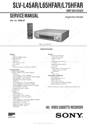
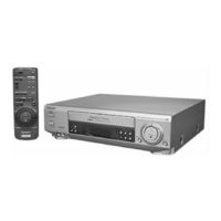
Video cassette recorder Sony SLV-L45AR; SLV-L65HFAR; SLV-L75HFAR
Brand:
Sony
| Category:
VCR
| Size: 12.96 MB
Table of Contents
Table of Contents
3
Section
5
General
5
Disassembly
13
Removal of Cabinet, Mechanism Unit and Main Board
13
Removing the Cabinet Parts
13
Removing the Mechanism Main Unit and the CP-1 PWB Assembly
13
Tel 13942296513
14
Installation of the Front Panel
15
Diagrams
16
Circuit Boards Location
16
Mechanism Connection Diagram
17
Overall Wiring Diagram (SLV-L45AR)
18
Overall Wiring Diagram (SLV-L65HFAR/L75HFAR)
19
System Control & Servo Circuit Diagram (SLV-L45AR)
20
System Control & Servo Circuit Diagram (SLV-L65HFAR/L75HFAR)
21
Audio & Video Circuit Diagram (SLV-L45AR)
22
Video & Audio Circuit Diagram (SLV-L65HFAR/L75HFAR)
23
Schematic Diagrams and Printed Wiring Boards
24
Board (PW-A) Power Supply Circuit Diagram
24
Board (VA-A) Video, Audio & Tuner Circuit Diagram (SLV-L45AR)
25
Board (VA-A) Video, Audio & Tuner Circuit Diagram (SLV-L65HFAR/L75HFAR)
26
Video Circuit Waveforms
27
Board Video Pre-Amp Circuit Diagram (SLV-L45AR)
27
Board Video Pre-Amp Circuit Diagram (SLV-L65HFAR/L75HFAR)
28
A7101 Display (FLD) Grid/Anode Assignment Drawing & Table
29
TM-1, 2 Boards Operation Key, Display & Timer Circuit Diagram (SLV-L45AR)
29
Ao y
29
Servo Circuit Waveforms
31
Ic301 System Control & Tuning Control Mpu Pin Functions Table
31
Board (SY-A) System Control & Servo Circuit Diagram (SLV-L45AR)
32
Board (SY-A) System Control & Servo Circuit Diagram (SLV-L65HFAR/L75HFAR)
33
Adjustments
35
Maintaining and Checking the Mechanism
35
L -1. Regular Checks and Maintenance Items
35
Regular Checks
35
Cleaning
35
Service Tools
36
Using the Relay Cable (J-6090-057-A)
37
An Overview of the Mechanism
37
Names of the Main Parts
37
Cassette Mechanism Assembly
37
Top View
38
Under Side
38
An Overview of the Mechanism Modes
39
Mechanism Mode Switching Table
39
Movement Check List for the Main Parts of the Mechanism
40
How to Check the Mechanism Mode Position
40
Self-Diagnosis Display
40
Q Q 3 6 7 3. Disassembling the Main Parts of the Mechanism
40
How to Make the Mechanism Move
41
How to Operate the Loading Motor Using a DC Voltage Supply
41
Operating the Loading Motor by the Manual Method
41
Making the Mechanism Move Using the Manual Method
41
Mechanism Unit
42
Cassette Drive Mechanism
42
Cassette Mechanism Assembly
42
Cassette Drive Gear
43
Door Opener, under Frame and Stand L
43
Start Rack Gear and Front Rack Gear
44
Cleaner Roller Assembly
44
Cylinder (DRUM)
45
Cylinder Motor (ROTOR and STATOR)
45
Cylinder Assembly
45
FE Head and ACE Head
46
Audio R/P Head Assembly (ACE Head) 2
46
Full Erase Head
46
Capstan Motor
47
Capstan Brake Assembly
47
Loading Motor Assembly and Worm Gear Assembly
48
Pinch Roller Pressure Mechanism
48
Pinch Roller Lever Assembly
48
Pinch Lift Cam and Pinch Cam Gear
49
Load Lever Assembly
50
BT Lever Assembly
50
Reel Drive Mechanism
51
Reel Belt, Reel Pulley, Friction Gear
51
Clutch Mounting Assembly
51
T Soft Brake Assembly, Take up Reel
52
Assembly, T Reel Gear
52
Section
52
Brakes
52
Brake Control Lever and Brake ACT Lever Assembly
53
Guides
54
Guide Roller Assembly
54
S and T Incline Mounting Assemblies
54
Wheel Gear 2, Main Cam and Mode Switch
55
Crescent Slide
55
S Load Gear, T Load Gear, S Load Lever Assembly Andt Load Lever Assembly
57
Tape Sensors, Reel Sensor and EP SW Lever
58
Tape Top Sensor and Tape End Sensor
58
Reel Sensor
58
EP Switch Lever
58
Mechanism Checks and Adjustments
59
Reel Table Torque Check
59
Adjusting the BT Lever Assembly Position and Checking the Back Tension Torque in Play Mode
59
BT Lever Pole Position Adjustment
59
Checking the Back Tension Torque
59
Tape Path Adjustment
60
Adjustment Procedure
60
Q Q
60
Load Lever Assembly Height Adjustment
60
Guide Roller Height Adjustment
61
Audio R/P Head (ACE HEAD) Height
62
Adjustment, Azimuth Adjustment and Horizontal Position Adjustment
62
Checking after Adjustment
63
Electrical Adjustments
64
Circuit Boards Location
64
Self-Diagnosis Display
65
Self-Diagnosis Contents and Mechanism Mode Display
65
Electrical Adjustment
67
Servo Circuit Adjustment
67
Test Equipment and Standards Required
67
Location of Adjustment Points
67
Video Circuit Relay Jig
69
Test Equipment and Standards Required
69
MTS Decoder Circuit Adjustment
70
SLV-L65HFAR/L75HFAR Only
70
Test Equipment and Standards Required
70
Location of Adjustment Points
70
IF Circuit Adjustment
73
Test Equipment and Standard Required
73
Location of Adjustment Point
73
Ao y U163
75
Advertisement
Sony SLV-L75HFAR Service Manual (87 pages)
VIDEO CASSETTE RECORDER
Brand:
Sony
| Category:
VCR
| Size: 8.9 MB
Table of Contents
Table of Contents
3
Section
5
General
5
Disassembly
13
Removal of Cabinet, Mechanism Unit and Main Board
13
Removing the Cabinet Parts
13
Removing the Mechanism Main Unit and the CP-1 PWB Assembly
13
Installation of the Front Panel
15
Diagrams
16
Circuit Boards Location
16
DIAGRAMS Circuit Boards Location
16
Mechanism Connection Diagram
17
Overall Wiring Diagram (SLV-L45AR)
18
Overall Wiring Diagram (SLV-L65HFAR/L75HFAR)
19
System Control & Servo Circuit Diagram (SLV-L45AR)
20
System Control & Servo Circuit Diagram (SLV-L65HFAR/L75HFAR)
21
Audio & Video Circuit Diagram (SLV-L45AR)
22
Video & Audio Circuit Diagram (SLV-L65HFAR/L75HFAR)
23
Schematic Diagrams and Printed Wiring Boards
24
Board (PW-A) Power Supply Circuit Diagram
24
Board (VA-A) Video, Audio & Tuner Circuit Diagram (SLV-L45AR)
25
Board (VA-A) Video, Audio & Tuner Circuit Diagram (SLV-L65HFAR/L75HFAR)
26
Video Circuit Waveforms
27
Board Video Pre-Amp Circuit Diagram (SLV-L45AR)
27
Board Video Pre-Amp Circuit Diagram (SLV-L65HFAR/L75HFAR)
28
A7101 Display (FLD) Grid/Anode Assignment Drawing & Table
29
TM-1, 2 Boards Operation Key, Display & Timer Circuit Diagram (SLV-L45AR)
29
TM-1, 2 Boards Operation Key, Display & Timer Circuit Diagram (SLV-L65HFAR/L75HFAR)
30
Servo Circuit Waveforms
31
Ic301 System Control & Tuning Control Mpu Pin Functions Table
31
Board (SY-A) System Control & Servo Circuit Diagram (SLV-L45AR)
32
Board (SY-A) System Control & Servo Circuit Diagram (SLV-L65HFAR/L75HFAR)
33
Adjustments
35
L -1. Regular Checks and Maintenance Items
35
Cleaning
35
Regular Checks
35
Maintaining and Checking the Mechanism
35
Service Tools
36
Using the Relay Cable (J-6090-057-A)
37
An Overview of the Mechanism
37
Cassette Mechanism Assembly
37
Names of the Main Parts
37
Top View
38
Under Side
38
An Overview of the Mechanism Modes
39
Mechanism Mode Switching Table
39
How to Check the Mechanism Mode Position
40
Movement Check List for the Main Parts of the Mechanism
40
Self-Diagnosis Display
40
Disassembling the Main Parts of the Mechanism
41
How to Make the Mechanism Move
41
How to Operate the Loading Motor Using a DC Voltage Supply
41
Making the Mechanism Move Using the Manual Method
41
Operating the Loading Motor by the Manual Method
41
Cassette Drive Mechanism
42
Cassette Mechanism Assembly
42
Mechanism Unit
42
Cassette Drive Gear
43
Door Opener, under Frame and Stand L
43
Cleaner Roller Assembly
44
Start Rack Gear and Front Rack Gear
44
Cylinder (DRUM)
45
Cylinder Assembly
45
Cylinder Motor (ROTOR and STATOR)
45
Audio R/P Head Assembly (ACE HEAD)
46
FE Head and ACE Head
46
Full Erase Head
46
Capstan Brake Assembly
47
Capstan Motor
47
Loading Motor Assembly and Worm Gear Assembly
48
Pinch Roller Lever Assembly
48
Pinch Roller Pressure Mechanism
48
Pinch Lift Cam and Pinch Cam Gear
49
BT Lever Assembly
50
Load Lever Assembly
50
Clutch Mounting Assembly
51
Reel Belt, Reel Pulley, Friction Gear Assembly and Clutch Change Lever
51
Reel Drive Mechanism
51
Assembly, T Reel Gear
52
T Soft Brake Assembly, Take up Reel
52
Section
52
Brakes
52
Assembly
53
Guides
54
S and T Incline Mounting Assemblies
54
Crescent Slide
55
Wheel Gear 2, Main Cam and Mode Switch
55
S Load Gear, T Load Gear, S Load Lever Assembly Andt Load Lever Assembly
57
Tape Sensors, Reel Sensor and EP SW Lever
58
Tape Top Sensor and Tape End Sensor
58
Reel Sensor
58
EP Switch Lever
58
Adjusting the BT Lever Assembly Position and
59
BT Lever Pole Position Adjustment
59
Checking the Back Tension Torque
59
Play Mode
59
Mechanism Checks and Adjustments
59
Reel Table Torque Check
59
Tape Path Adjustment
60
Adjustment Procedure
60
Load Lever Assembly Height Adjustment
60
Guide Roller Height Adjustment
61
Audio R/P Head (ACE HEAD) Height
62
Adjustment, Azimuth Adjustment and Horizontal Position Adjustment
62
Checking after Adjustment
63
Circuit Boards Location
64
Electrical Adjustments
64
Self-Diagnosis Contents and Mechanism Mode Display
65
Self-Diagnosis Display
65
Electrical Adjustment
67
Servo Circuit Adjustment
67
Test Equipment and Standards Required
69
Video Circuit Relay Jig
69
Test Equipment and Standards Required
70
MTS Decoder Circuit Adjustment
70
SLV-L65HFAR/L75HFAR Only
70
Location of Adjustment Points
70
Audio Output Mode and Output Signal Check
72
IF Circuit Adjustment
73
Test Equipment and Standard Required
73
Location of Adjustment Point
73
Advertisement
Related Products
Sony POWER TRILOGIC SLV-L72HF PA
Sony POWER TRILOGIC SLV-L79HF CL
Sony SLV-L7HFCS
Sony SLV-L7HFPX
Sony SLV-L7HFPA
Sony SLV-L77HF
Sony SLV-L78HF
Sony SLV-L76HFAR
Sony SLV-L7OHFCS
Sony SLV-L7OHFMX
Sony Categories
Laptop
TV
Camcorder
CD Player
Digital Camera
More Sony Manuals
Login
Sign In
OR
Sign in with Facebook
Sign in with Google
Upload manual
Upload from disk
Upload from URL