Sign In
Upload
Manuals
Brands
Siemens Manuals
Control Unit
LMV52.440B1
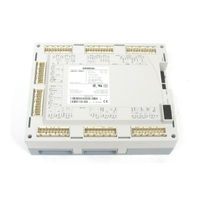
Siemens LMV52.440B1 Management System Manuals
Manuals and User Guides for Siemens LMV52.440B1 Management System. We have
4
Siemens LMV52.440B1 Management System manuals available for free PDF download: Technical Instructions, Manual
Siemens LMV52.440B1 Manual (327 pages)
Brand:
Siemens
| Category:
Computer Hardware
| Size: 8.28 MB
Table of Contents
Table of Contents
3
Safety Notes
10
Warnings
10
Mounting Notes
12
Installation Notes
14
Electrical Connection of Ionization Probe and Flame Detector
15
Commissioning Notes
15
Setting and Parameterization Notes
16
Standards and Certificates
17
Service Notes
19
Life Cycle
19
Disposal Notes
19
General
20
Brief Description
20
Block Diagram of Inputs / Outputs
22
Fuel Train (Examples)
25
Burner Control
32
Description of Inputs and Outputs
32
Flame Signal Input and Flame Detector
32
Self-Test Function LMV5 / QRI / QRA7
32
Separate Flame Supervision (Only LMV50 / LMV52)
33
QRI (Suited for Continuous Operation)
34
Ionization (Suited for Continuous Operation)
34
QRA2 / QRA4 / QRA10 with AGQ1 (for Intermittent Operation Only)
35
QRA7 (Suited for Continuous Operation)
37
QRB (for Intermittent Operation Only)
38
Standardization of Flame Signal Display AZL5
39
Configuration Extraneous Light
39
External Flame Supervision (LMV50 / LMV52)
40
High Temperature Supervision (Only LMV50)
41
Digital Inputs
42
Safety Loop / Burner Flange (X3-04 Pin 1 / X3-03 Pin 1)
42
Manual Lockout / Reset
43
Fuel Selector (X4-01 Pin 1 / X4-01 Pin 2)
44
Fan Contactor Contact / Flue Gas Recirculation Pressure Switch (X4-01 Pin 3)
44
External Boiler Controller ON/OFF = Heat Request (X5-03 Pin 1)
46
External Boiler Controller OPEN/CLOSED or STAGE2 / STAGE3
47
X5-03 Pin 3)
47
Air Pressure Switch (X3-02 Pin 1)
48
Gas Pressure Switch - Valve Proving or Valve Closure Contacts (X9-03 Pin 2)
48
Gas Pressure Switch-Min (X9-03 Pin 4)
50
Start Release - Gas / CPI (X7-03 Pin 2)
51
Gas Pressure Switch-Max (X9-03 Pin 3)
53
Oil Pressure Switch-Min (X5-01 Pin 2)
53
Oil Pressure Switch-Max (X5- 02 Pin 2)
54
Start Release - Oil (X6-01 Pin 1)
54
Heavy Oil - Direct Start (X6-01 Pin 3)
55
Digital Outputs
56
Alarm, Type No-SI (X3-01 Pin 2)
56
Fan, Type No-SI (X3- 01 Pin 1)
56
Ignition, Type si (X4-02)
56
Oil Valves, Type si (X8-02, X8-03, X7-01, X7-02, X6-03)
57
Gas Valves, Type si (X9-01)
57
Operation Indication Gas / Oil, Type si (X8-01)
57
Oil Pump / Magnetic Clutch, Type No-SI (X6-02)
58
Start Signal or Pressure Switch Relief Valve, Type No-SI (X4-03)
58
Control Sequence
59
Parameters
59
Time Parameter
59
Reaction Time for Loss of Flame / Safety Time in Operation
59
Gas Valve Proving
61
Special Functions During the Control Sequence
63
Lockout Phase (Phase 00) / Safety Phase (Phase 01)
63
Repetition Counter
64
Signaling of Start Preventions
65
Safety Shutdown in Standby Mode
65
Forced Intermittent Operation
65
Prepurging
66
Program Stop Function
67
Gas Shortage Program
67
Low-Fire Shutdown
68
Normal / Direct Start
68
Continuous Fan Operation
69
Continuous Pilot (Only LMV50 / LMV52)
69
Reaction of Extraneous Light in Standby
69
Startup Sequence Stop in Phase 36
70
Cooling Function in Standby Mode (Only LMV50)
70
Long Postpurge Time (Only LMV50 / LMV52.4)
70
Selection of Fuel
71
Auxiliary Functions
72
Hours Run Counter
72
Start Counter / Startup Counter
72
End of Life Cycle Function
72
Fuel Meter
72
Sequence Diagrams
73
Fuel-Air Ratio Control (FARC)
84
Actuator Addresses
84
Activating / Deactivating the Actuators
85
Direction of Rotation of the Actuators
86
Control Sequence
87
Idle Position
87
Prepurge Positions
87
Ignition Positions
87
Startpoint Operation
88
Approaching Low Fire in Phase 50 / 54
89
Postpurge Positions
90
Actuator Speed Outside Normal Operation = Tmnoflame
90
Actuator Speed in Normal Operation = Operatrampmod
91
Multistage Operation
92
Position Check, Dynamic Safety Time
93
Special Features
96
Program Stop
96
Limitation of Load Range
97
Masking out a Load Range
98
Traveling Times
98
Shutdown Behavior
98
Overload Protection
99
Boiler Controller / Load Controller
100
General
100
Connection Diagram
100
Operating Modes Load Controller
101
Manual / Automatic Burner Startup
106
Operating Mode Changeover to Internal Load Controller
107
Control (Characteristics)
108
Integrated 2-Position Controller (R = ON/OFF)
108
Modulating Control
109
Manual Setting of the PID Control Parameters
110
Adaption / Self-Setting of PID Controller Parameters
111
Multistage Control
115
Actual Values (X)
117
Setpoints (W)
120
Integrated Temperature Limiter Function
123
Cold Start Thermal Shock Protection (CSTP)
125
Cold Start Thermal Shock Protection - Modulating Operation
125
Cold Start Thermal Shock Protection - Multistage Operation
126
Cold Start Thermal Shock Protection with Temperature Sensor in Pressure Plants
127
Analog Output X63 (0(4)
128
Multiboiler Plants
129
Multiboiler Plants by Means of Analog Input
129
Multiboiler Plants by Means of Digital Interface
129
Display and Operating Unit AZL5
130
Assignment of AZL5 Terminals
131
Ports of the AZL5
133
Port for the PC
134
Interface to BACS
135
General Information and BACS Functions
135
Modbus
135
Interface for the Output of Trending Data
138
Displays and Settings
139
Menu Structure
139
Display of Normal Operation
140
Lockout and Error Messages
143
Example: Display of Lockouts in the Lockout History
143
Standard Parameterizations (Inclusive Entry of Password)
145
Addressing / Function Assignment of Actuators
149
Setting the Fuel-Air Ratio Control Curves
151
Adjusting the Curves by Introducing or Editing an Individual Point
152
Curve Setting Via Manual Operation
156
Setting Modulating Ratio Control
159
Setting Multistage Ratio Control
159
Adaption of the Load Controller's PID Parameters
161
Burner Identification / Backup - Restore
163
Languages
163
Real Time Clock / Calendar, Automatic Summer / Wintertime Changeover
164
Adjustment of Contrast, Shut-Off, Quick Access
164
TÜV Test
165
Commissioning Instructions for the LMV5
166
Basic Configuration
166
Settings for Gas-Fired Operation
171
Settings for Multistage Oil-Fired Operation
176
Extra Functions of the LMV5
181
Configuring the Load Controller
183
Control Parameters of the Load Controller
185
Connection Terminals / Coding of Connectors
190
Connection Terminals Lmv51.040X1
190
Connection Terminals Lmv51.000X1 / Lmv51.000X2 / Lmv51.040X2
191
Connection Terminals Lmv51.140X1
192
Connection Terminals Lmv51.100X1 / Lmv51.100X2 / Lmv51.140X2
193
Connection Terminals Lmv51.300X1 / Lmv51.300X2 / Lmv52.200X1 / Lmv52.200X2 / Lmv52.240X2 / Lmv52.400X1 / Lmv52.400X2
194
Connection Terminals Lmv51.340X1 / Lmv52.240X1 / Lmv52.440X1 / Lmv52.440X2
195
Coding of Connectors
196
Description of Connection Terminals (AC 120 V)
199
Description of Connection Terminals (AC 230 V)
206
Mounting , Electrical Installation and Service
213
Power Supply to the LMV5
214
Examples of Various Installation Situations
215
Determination of the Maximum Cable Length AGG5.6
219
When Is a Second AGG5.2 Power Transformer Required
223
Suppliers of Other Accessory Items
224
Mounting Clip for Mounting Rail
224
Ebus PC Adapter
224
RS232-USB Adapter (Connection AZL52 to PC for Using the ACS450 PC Software)
224
Mechanical Coupling
224
Duties of the Authorized Inspector
225
Technical Data
229
LMV5 and AZL5
229
Loads on Terminals, Cable Lengths and Cross-Sectional Areas
230
Cross-Sectional Areas
232
AZL5 Display and Operating Unit
232
CAN Bus Cable
233
Environmental Conditions (for All LMV5 Components)
233
Dimensions
234
Block Diagram of Contact Links
237
VSD Module
238
VSD Module
239
Inputs / Outputs
239
Configuring the VSD
243
Configuring Speed Acquisition
243
Speed Standardization
244
Configuring the Current Interface
245
Configuring the Fuel Meter
245
Fuel Meter Readings
246
Process Data
247
Emc: Lmv5 - Vsd
248
Connection Terminals
249
Description of Connection Terminals for the VSD Module
250
O2 Trim Control with LMV52 and PLL52
251
General
251
Functioning Principle of O2 Trim Control
252
Air Rate Change
252
Definition of O2 Setpoint
253
Lambda Factor
253
Precontrol
254
Calculation of Precontrol
254
O2 Trim Control
255
Operating Modes of O2 Trim Controller / O2 Alarm
255
Load Limitation with O2 Trim Control
257
Startup
257
Heating up the QGO20 Sensor after Power on
257
Burner Start Mode for O2 Trim Control (Only LMV52.4, Only in Operating Modes O2 Control and Conautodeac)
258
Initializing and Release of the O2 Trim Controller
259
Modulation Release on Startup
261
Behavior in the Event of Load Changes (Dynamic Release Criterion)
261
Increasing the Manipulated Variable in Case of Fast Load Changes (O2Modoffset, Formerly O2Offset)
262
Control Interventions (Switching Functions) by the O2 Trim Controller
263
O2 Trim Control Behavior
263
Limiting the O2 Trim Controller Manipulated Variable with Shutdown
264
Deactivating O2 Trim Control Via a Contact
266
Displaying the O2 Trim Controller Status
267
O2 Alarm
268
Delayed O2 Limit Value
268
Switch-Off Criteria of the O2 Alarm
269
O2 Minimum Value Alarm
269
O2 Maximum Value Alarm
270
Inactivation / Deactivation of the O2 Alarm
270
Self-Test
271
O2 Sensor Test
271
Checking the O2 Content (20.9%)
272
Auxiliary Functions
273
Warning When Flue Gas Temperature Is too High
273
Combustion Efficiency
273
Service Timer for QGO20
274
PLL52 O2 Module
275
Inputs and Outputs
275
CAN Bus X84, X85
278
Configuring the PLL52
278
Configuring the System
279
Actuators / Vsds
279
Parameterizing the Type of Fuel
279
Setting the User-Defined Type of Fuel
280
Commissioning the O2 Trim Control System
281
Setting Fuel-Air Ratio Control
281
Setting the O2 Alarm
281
Direct Entry of O2 Min. Values
282
Measuring the O2 Min. Values by Lowering the Air Rate
282
Setting O2 Trim Control
283
Checking and Changing the Controller Parameters
284
Setting Notes
285
Parameterizations
285
Setting Fuel-Air Ratio Control
285
Setting the O2 Trim Controller
287
Other Notes
287
Technical Data
288
Loads on Terminals, Cable Lengths and Cross-Sectional Areas
288
Flue Gas Recirculation (FGR) Function (LMV50/LMV51.3/LMV52)
289
Function Principle of Flue Gas Recirculation (FGR)
289
Parameter for the Flue Gas Recirculation (FGR) Function
291
Setting Electronic Fuel-Air Ratio Control in Connection with Flue Gas Recirculation (FGR)
295
Settings in Time or Temperature Mode (Without Temperature Compensation)295
295
Settings in Temperature-Compensated Mode (Only LMV52.4)
297
Settings in Deactminpos or Auto Deact Mode (Only LMV52.4)
300
Reading the Flue Gas Recirculation (FGR) Operating Temperature (Only LMV52.4)
301
Dimensions
302
Revision History
303
Changes of LMV51 from Series a to B
303
Changes in the LMV5 Release Upgrade
303
Changes to Basic Unit LMV5
303
Basic Unit LMV51; Software from V02.10 in V02.20
303
Basic Unit LMV52, Introduction V01.10
304
Basic Unit LMV51, Software from V02.30 to V02.50
304
Basic Unit LMV52, Software from V01.30 to V04.10
305
Basic Unit LMV52, Software from V04.10 to V04.20
305
Basic Unit LMV52, Software from V04.20 to V04.50
306
Basic Unit LMV52, Software from V04.50 to V04.80
306
Basic Unit LMV52.4, Software from V04.80 to V10.00
307
Software Versions of the 2012/2013 Release Upgrade
307
Basic Unit LMV51.0 and LMV51.1, Software from V02.50 to V05.10
308
Basic Unit LMV51.3, Software from V04.80 to V05.10
309
Basic Unit LMV50, Relaunch with V10.20 Software
309
Basic Unit LMV52.2, Software from V04.80 to V05.10
310
Basic Unit LMV52.4, Software from V10.00 to V10.20
311
Basic Unit LMV5, Software from V05.10 to V05.20, 10.20 to V10.30
311
Changes to the Load Controller
312
Load Controller, Software from V01.40 to V01.50
312
Load Controller, Software from V01.50 to V01.60
313
Load Controller, Software from V01.60 to V01.80
313
Load Controller, Software from V01.80 to V02.10
313
Load Controller, Software for 2012/2013 Release Upgrade
313
Changes to the Variable Speed Drive Module (VSD Module)
314
VSD Module, Software from V01.30 to V01.40
314
VSD Module, Software from V01.40 to V01.50
314
VSD Module, Software for 2012/2013 Release Upgrade
314
Changes to the Display and Operating Unit AZL52
315
Display and Operating Unit AZL5, Software from V2.20 to V02.50
315
Display and Operating Unit AZL52, Software from V04.00 to V04.10
316
Display and Operating Unit AZL52, Software from V04.10 to V04.20
316
Display and Operating Unit AZL52, Software from V04.20 to V04.30
316
Display and Operating Unit AZL52, Software from V04.30 to V04.50
317
Display and Operating Unit AZL52, Software from V04.50 to V04.60
317
Display and Operating Unit AZL52, Software from V04.60 to V04.80
317
Display and Operating Unit AZL52, Software from V04.80 to V05.00
318
Display Unit and Operating Unit AZL52, Software from V05.00 to V05.10
318
Index
320
Advertisement
Siemens LMV52.440B1 Technical Instructions (374 pages)
Linkageless Burner Management System
Brand:
Siemens
| Category:
Control Systems
| Size: 16.67 MB
Table of Contents
3-2: Parameter List
60
Table of Contents
60
Lockouthistory
63
Gasfiring
64
Mint_Prepurgegas
65
Interval1Gas
66
Maxtmelowfire
67
Ignoilpumpstart
68
Mainsfrequency
69
Startreleasegas
70
Gaspressuremax
71
Heavyoildirstart
72
Standardfactor
73
Heavyoil
74
Homepos
75
Ignitionpos
76
Maxloadgas(Oil)
77
Loadmaskhighlim
78
Numfuelactuators
79
O2 Alarm
80
High-Fire
81
Loadctrlsuspend
82
O2Maxmanvariable
83
Load of Ignition
84
O2 Content Air
85
Manvar O2 Ctrl
86
Part
87
Minactuatorstep
88
Stageload
89
Maxtmemod
90
Mrange Presssens
92
Startadaption
93
Language
94
Addressing
95
Setteling Time
97
Max Stat Dev
98
Maxtempflgasgas
99
Thresholdfgr Gas(Oil)
100
Operationtempgas(Oil)
101
Gasfiring
102
OEM Password
103
Load_Sw_From_Pc
104
Section 4: Commissioning
119
120
Pre-Requisites for Basic LMV51 Systems
120
Pre-Requisites for LMV52 Systems with a VFD
122
Pre-Requisites for LMV52 Systems with O 2 Trim
123
Configuring (Parameterization Of) an LMV5 with a Default Parameter Set
124
Transferring Parameter Sets Using the AZL Display
132
Suggested Initial Light-Off for LMV5 Systems
133
Suggested Ratio Control Curve Commissioning
135
Suggested Load Control Setup
140
Suggested Cold Start (Thermal Shock Protection) Setup
142
Additional Tips for Commissioning
146
Special Features and Settings
148
Section 5 - Variable Speed Drive Control
153
154
Introduction
154
VFD and AC Induction Motor Fundamentals
154
Line Reactors
155
Output Wiring / Load Reactors
156
Shaft Current
157
Braking Resistors
157
Types of Vfds: Vector and Volt/Hz
159
Centrifugal Blower Fundamentals
159
Configuring Vfds for Use with the LMV52
160
Standardizing the LMV52
161
Blower Speed Monitoring
165
Suggested Setup Procedure for the VFD Control
167
Additional Tips for Burners with VFD Control
168
Section 6: Oxygen Trim
173
Introduction
174
O 2 Trim (O 2 Control) Fundamentals
174
174
Pre-Control
176
O 2 Trim Terminology
176
O 2 Control and O
178
Control and O Alarm Curves
178
O 2 Trim Configuration (Parameterization) before Commissioning
179
Suggested O 2 Trim Commissioning - Traditional Nozzle Mixing Burner with no or Low Percentage FGR (Typically LMV52.240)
181
Suggested O 2 Trim Commissioning - Premix Mesh Burner or Nozzle Mixing Burner with High Percentage of FGR (Typically LMV52.440)
186
Post Commissioning Tuning
192
Observing the Behavior of the O 2 Trim
196
Using the O Alarm Functionality Without O Trim
197
How the O 2 Is Measured with the QGO20 Sensor and PLL52 Module
198
Considerations When Using O Trim with FGR
201
7-1: Troubleshooting Introduction
209
Canbus Faults Including "AZL Not on Bus" and "System Test
210
CanbusFaultsIncluding“AzlNotOnBus”And“SystemTest”
215
Fault Positioning Actuator - Error Code 15
215
Internal Fault Actuator - Error Code 19
215
Flame Failure - Error Code 25 or 26
216
Open Circuit / Short Circuit Sensor Faults - Error Code A6 (Diagnostics 50
217
Open Safety Loop - Error Code 21
218
LMV5 will Not Start (Stays in Phase 12)
219
LMV5 will Not Modulate Properly
220
221
O 2 Sensor Is Not Reading
221
O 2 Sensor Reading Grossly High or Low
222
O 2 Sensor Reads but Responds very Slowly
222
Ambient or Stack Temperature Sensor Reading Incorrectly
223
AZL Says "O2 Module Not Active or Not Available
223
AZL Says "O2 Setpoint Must Lie 0.1% below O2 Ratio Control" or "O2 Setpoint Must Lie 0.1% above O2 Min
224
AZL Says "Measurement Not Successful" When Measuring the Delay Time for O 2 Trim
225
AZL Says "O2 Trim Control Automatically Deactivated
226
227
VSD will Not Operate
227
Unsuccessful VSD Standardization
228
AZL Says "Fan Speed Not Reached" or "Control Range Limitation VSD Module
230
10-1: Introduction
309
Table of Contents
310
Section 10-2: LMV51 Software Version Updates
310
LMV51 Version 0210 to 0220
310
LMV51 Version 0230 to 0250
312
LMV51 Version 0250 to 0510
312
LMV51 Version 0510 to 0520
314
Load Controller Version 0140 to 0150
314
Load Controller Version 0150 to 0160
315
Load Controller Version 0160 to 0180
315
Load Controller Version 0180 to 0210
316
Section 10-3: LMV52 Software Version Updates
317
LMV52 Version 0130 to 0410
317
LMV52 Version 0410 to 0420
318
LMV52 Version 0420 to 0450
319
LMV52 Version 0450 to 0480
319
LMV52 Version 0480 to 0510
320
LMV52 Version 0510 to 1020
321
LMV52 Version 1020 to 1030
321
Load Controller Version Updates
321
VSD Module Version 0130 to 0140
322
VSD Module Version 0140 to 0150
322
Table of Contents
332
Direct Start
334
Introduction
334
Procedure
334
Operation
336
Hot Standby on a Steam Boiler with an RWF50 or RWF55
337
Introduction
337
Hot Standby with a Temperature Switch
342
Introduction
342
Procedure
343
Operation
343
Low Fire Hold with an RWF55
344
Introduction
344
Hot Water Boiler with an RWF55 with 3-Position Output
344
Hot Water Boiler with an RWF55 with Analog Output
344
Steam Boiler with an RWF55 with 3-Position Output
344
Steam Boiler with an RWF55 with Analog Output
344
Operation
349
Example
349
Pilot Valve Proving
350
Introduction
350
Procedure
350
Option 1: on Startup with Skp25'S on both the Pilot and Main Gas Trains
350
Important Notes
353
Sequence of Operation
353
Option 2: on Startup, SKP25 on the Main Gas Train, Solenoid Valves on the Pilot Train
354
Important Notes
355
Sequence of Operation
355
Option 3: Pilot Valve Proving on Startup and Main Valve Proving on Shutdown
356
Important Notes
357
Sequence of Operation
357
Purge Proving
358
Introduction
358
Procedure
358
Operation
359
Remote Setpoint
360
Introduction
360
Procedure
360
Example: Pressure Sensor Wired to Terminal X61
362
Example: Temperature Sensor Wired to Terminal X60
363
Example: Temperature Transmitter Wired to Terminal X61
364
Valve Proving with Two Pressure Switches
365
Introduction
365
Sequence of Operation
366
Important Notes
366
VFD Bypass
367
Introduction
367
Single Fuel Procedure
368
Single Fuel Operation
370
Dual Fuel Procedure
371
Dual Fuel Operation
372
Siemens LMV52.440B1 Manual (39 pages)
Burner Management System
Brand:
Siemens
| Category:
Control Unit
| Size: 1.28 MB
Advertisement
Siemens LMV52.440B1 Manual (29 pages)
Burner Management System
Brand:
Siemens
| Category:
Control Systems
| Size: 0.93 MB
Advertisement
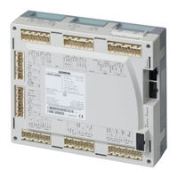
Related Products
Siemens LMV52.4 series
Siemens LMV52.400B2
Siemens LMV52 series
Siemens LMV52.200B1
Siemens LMV52.240B1
Siemens LMV52.240B2
Siemens LMV52.200B2
Siemens LMV52.200A1
Siemens LMV52.200A2
Siemens LMV52.240A1
Siemens Categories
Industrial Equipment
Controller
Control Unit
Oven
Washer
More Siemens Manuals
Login
Sign In
OR
Sign in with Facebook
Sign in with Google
Upload manual
Upload from disk
Upload from URL