Sign In
Upload
Manuals
Brands
Panasonic Manuals
Controller
GM1 Series
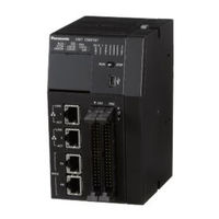
Panasonic GM1 Series Motion Controller Manuals
Manuals and User Guides for Panasonic GM1 Series Motion Controller. We have
7
Panasonic GM1 Series Motion Controller manuals available for free PDF download: User Manual, Reference Manual
Panasonic GM1 Series User Manual (650 pages)
Motion Controller Controller RTEX
Brand:
Panasonic
| Category:
Controller
| Size: 13.92 MB
Table of Contents
Table of Contents
7
1 Before Using this Product
17
Safety Precautions
18
Handling Precautions
19
Software License Agreement
20
2 Operation Flow
23
System Configuration Diagram
24
Work Flowchart
26
3 Overview of the GM Programmer
29
System Requirements
30
Usage Environment of the GM Programmer
30
Installation and Uninstallation
31
Installing GM Programmer
31
Uninstalling GM Programmer
35
Basic Operations
36
How to Start
36
How to Quit
37
Component Names
38
Menu Bar
38
Toolbar
45
Navigator Pane
49
Main Pane
50
Status Bar
51
Window Operations
53
Moving the Pane Location
53
Showing / Hiding Panes
55
Switching the Tab of the Main Pane
56
Full-Screen Display
58
Switching the Object Window
59
Operating the Object Window
59
Other Functions
60
Option Setting Function
60
Display Language Setting Function
61
Online Help Function
62
Version Display Function
63
4 Project Operations
67
Creating a New Project
68
Saving a Project
71
Opening a Project
72
Closing a Project
73
Device Tree Configuration
74
Project Configuration
76
Adding an Object
77
Adding Objects
78
Adding Devices
82
Setting up a Project
84
Exporting and Importing Objects
86
Exporting Objects
86
Importing Objects
87
Creating a Backup When a Project Is Saved
90
Automatically Saving Project Files
92
Printing a Project
94
Printing an Object Within a Project
96
Comparing Projects
97
Project Comparison Method
97
Merging Differences
100
5 Project Creation
103
Project Creation Flow
104
Setting up the GM1 Controller
105
Setting up Motion Control
107
Setting up RTEX Master
107
Adding and Setting up Servo Amplifiers
108
Adding and Setting up Free Encoder and Virtual Drive
111
Setting up Unit Control
115
Setting up General-Purpose I/O, PWM Output, and High-Speed Counter for GM1 Controller
115
Adding Expansion Units
117
Setting up the Communication Function
121
Adding a Protocol to be Used for the LAN Port
121
Adding a Protocol to be Used for the COM Port
124
6 Program Creation
129
Flow of Program Creation
130
Program Creation Window
131
Main Pane
131
Declaration Editor
131
Auto Declaration
133
Toolbox
135
Setting up the Program Input Window
136
Window Operations for the Program Input Window
140
Creating a Program Object (POU Object)
142
Types of Programming Language
143
Variables
146
Standard Data Types
146
Array
147
Subrange Types
147
Structure, Enumeration, Alias, and Union Data Types
148
Constants
152
Object for Global Variable Declaration
152
Global Variables
153
Persistent Variables
155
Short Form Function
158
Function and Function Block
160
Function
160
Function Block
164
Entering Programs in each Programming Language
168
7 Entering Programs in each Programming Language
169
Programming in Ladder Diagram (LD)
169
Inserting Contacts, Coils, and Function Blocks
169
Inserting Contacts in Parallel
174
Inserting a Network (Circuit)
175
Inserting a Branch
176
Input of Title and Comment (LD)
177
Commenting out a Network (Circuit)
179
Programming in Structured Text (ST)
181
ST Program Syntax
181
Commenting out Code in ST Program
183
Programming in Sequential Function Chart (SFC)
185
Inserting Elements from Menu
185
Inserting Elements from Toolbox
187
Inserting Elements from Toolbar
188
Setting up the SFC Editor
189
Setting SFC Program Execution Conditions
191
Programming in Function Block Diagram (FBD)
193
Entering Function Blocks
193
Inserting and Commenting out a Network (Circuit)
198
Input of Title and Comment (FBD)
198
Settings in FBD Program
198
Programming in Instruction List (IL)
200
Entering Instructions and Operands
200
Settings in IL Program
202
Programming in Continuous Function Chart (CFC)
204
Inserting and Connecting Elements
204
Connection Mark
209
Program Creation Support Functions
210
Bookmark
210
Call Tree View
210
Cross Reference List View
211
Function Block Guidance
212
Input Assistant Function
216
Argument / Variable Input Support (Component List)
217
Global Renaming (Refactoring)
218
Displaying Programs in Multiple Languages (Project Localization)
221
Build
225
Rebuild
225
Code Generation
225
Clean
226
Clean All
227
Tasks
228
Adding Programs
228
Adding a Usertask
233
Task Configuration Window
235
Connecting the GM1
238
Flow of Operation Check
238
8 Connecting the GM1 Controller and PC
239
Selecting a Connection Port for GM Programmer
239
Connecting the GM1 Controller and PC with a Cable
239
Operation When Power Is on
239
Operation Mode Switching
241
Communication Setting
242
Addition of the USB Port
242
Setting the LAN Port
243
Connecting to the GM1 Controller
246
Setting Time
248
Other Settings
250
Changing the Device Name
250
Sending Echo Services
251
Device Preference Management
252
Confirmed Online Mode
254
Login / Logout
256
Login
256
Logout
257
Download
257
Online Change
259
Code Analysis (Static Analysis Light)
259
Source Upload
263
Commissioning
265
Online Config Mode
265
Conducting Commissioning for Servo Amplifiers
266
9 Debug
271
Running and Stopping the GM1 Controller
272
Single Cycle
273
Breakpoint
275
Setting a Breakpoint
275
Setting an Execution Point
276
Call Stack View
278
Debug Operations
280
Writing Values and Forcibly Changing Values
280
Watch
281
Flow Control
282
Operation Mode
284
Monitoring Function
285
Reset
288
Reset Warm, Reset Cold, and Reset Origin
289
Executing Device Reset from GM Programmer
289
Executing Device Reset from GM1 Controller
290
Checking the Status of GM1 Controller
292
Checking Logs
292
Checking the Status
293
Checking the System Data History
294
Task Monitoring
295
Device Trace Function
296
Device Trace Function
297
Checking the Performance of GM1 Controller
303
Performance Check Based on Cycle Time
303
Performance Check Based on Device Trace
304
Error Notification Function
306
Overview of Errors
306
Checking and Clearing Errors Using GM Programmer
306
Obtaining Error Information Using User Programs
307
Error Recovery Processing
309
Error Code List
310
10 Useful Functions of GM Programmer
315
Simulation Function
316
Security Function
317
Security Function: User Management
318
Project User Management
318
Creating a New User and Group
318
Setting Operation Privileges
322
Performing Operation with Privileges Set
324
Device User Management
325
Security Function: Encryption
330
Encrypting Project Files
330
Encrypting the Communication Path: Encrypting Communications Using the Certificate Possessed by the GM1 Controller
331
Encrypting the Communication Path: Encrypting Communications Using a Created Certificate
334
Security Function: Write-Protection
339
Opening Files in Read-Only Mode
339
Setting the "Released" Flag
339
User Library Function
341
Creating a Library and Adding to the Library Repository
341
Using Created Libraries
345
POU for Implicit Checks
347
Setting up POU for Implicit Checks
347
Interface
349
Setting up an Interface Object
349
Implementing in New Function Block
351
Implementing in Existing Function Block
353
Extending the Interface
356
External File Functions
359
Setting up an External File Object
359
Servo Amplifier / Motor Operation Function (PANATERM Lite for GM)
361
Starting PANATERM Lite for GM
361
Motion Control
364
11 Motion Control
365
RTEX Axis Setting
365
Overview of RTEX Axis Setting
365
Basic Settings of the RTEX Axis
365
RTEX Axis Extended Setting
368
Basic Preparations for Operation
376
Overview of Basic Preparations for Operation
376
Servo on or off
376
Home Return
377
JOG Operation
386
Single-Axis Operation
388
Overview of Single-Axis Operation
388
Position Control
388
Switching the Control Mode
395
Velocity Control
396
Torque Control
398
Stop
400
Synchronous Operation
402
Synchronous Cam Operation
402
Synchronous Gear Operation
408
Multi-Axis Operation
411
Overview of Interpolation Control
411
Linear Interpolation and Circular Interpolation
412
How to Use Interpolation Control
413
Registering a CNC Table
414
Overview of G-Code
425
G-Code Editor and Coding Rules
426
Movements Executed by each G-Code and Setting Methods
427
SMC_CNC_REF and SMC_OUTQUEUE
439
Interpolation Operation Programming: How to Create a Program for Executing Operation
440
Interpolation Operation Programming: Explanation of Function Block (FB)
443
Interpolation Operation Programming: Specifying the Starting Coordinates
446
Interpolation Operation Programming: P-Point Control and C-Point Control
450
Interpolation Operation Programming: Settings in CNC Table for C-Point Control
452
Interpolation Operation Programming: Settings in POU for P- Point Control and C-Point Control
453
Interpolation Operation Programming: Joining and Repeating CNC Tables
454
Interpolation Operation Programming: Changing Parameter Settings (Converting to Variables in CNC Table)
457
Motion Function Errors
459
Overview of Motion Function Errors
459
Error Check Method
460
Clearing Errors
461
12 Unit Control
464
Overview of Unit Control
464
Unit Control
464
IO Parameters for Unit Control
465
I/O Mapping for Unit Control
466
General-Purpose I/O
467
Overview of General-Purpose I/O Function
467
Setting Parameters with GM Programmer
467
Setting Items of Io_Configuration Parameters
468
I/O Mapping for General-Purpose I/O
469
PWM Output
471
Overview of PWM Output
471
Setting Output Ports with GM Programmer
471
I/O Mapping for PWM Output
472
Data Update Timing (Output Frequency)
473
Data Update Timing (Duty Ratio)
474
PWM Output Setting Example
474
High-Speed Counter Function
480
Overview of High-Speed Counter Function
480
Setting Parameters with GM Programmer
481
Counter Parameter Setting Items
484
I/O Mapping for High-Speed Counter Output
487
Operation Ready Request
490
Count Function
493
Comparison Function
503
External Output Function
509
Capture Function
510
Unit Error
522
Settings of I/O Unit
524
Parameter Settings
524
I/O Mapping for I/O Unit
524
13 Communication Function
527
Overview of Communication Function
528
Adding Network Communication Devices
528
Adding Serial Communication Devices
529
General-Purpose Communication
532
General-Purpose Communication (Ethernet)
532
General-Purpose Communication (Serial)
533
General-Purpose Communication (Serial)
546
Modbus
550
What Is Modbus TCP
550
Modbus-TCP Master Communication
550
Modbus-TCP Slave Communication
554
Modbus-RTU Master Communication
556
Modbus-RTU Slave Communication
564
Ethernet/Ip
568
What Is Ethernet/Ip
568
Cyclic Communication Function
568
Ethernet/Ip Scanner Function
568
Setting up the Ethernet/Ip Scanner Function
568
Ethernet/Ip Scanner Operation
575
Ethernet/Ip Adapter Function
577
Setting up the Ethernet/Ip Adapter Function
577
Ethernet/Ip Adapter Operation
581
14 Other Controller Functions
584
SD Card Access
584
Overview of SD Card Access Function
584
File Manipulations Using the CAA File Library
584
Time Function
592
Overview of Time Function
592
Settings Based on GM Programmer
592
Settings Based on Function Blocks
592
Trace Function
593
Setting up Trace
593
Executing Trace
596
Advertisement
Panasonic GM1 Series Reference Manual (166 pages)
Motion Controller
Brand:
Panasonic
| Category:
Controller
| Size: 6.34 MB
Table of Contents
Table of Contents
7
1 Before Using this Product
11
Safety Precautions
12
Handling Precautions
13
2 Functions of Unit and Restrictions on Combination
15
Unit Functions and How They Work
16
Functions of the Unit
16
Unit Type and Product Number
17
Restrictions on Combinations of Units
18
Unit Combinations for Positioning Control
18
Restriction by Power Consumption
19
Applicable Versions of Unit and Software
19
Names and Functions of Parts of the GM1 Pulse Output Unit
20
3 Wiring
23
Precautions on Wiring
24
Connection Using the Discrete-Wire Connector
25
Specifications of Discrete-Wire Connector
25
Wiring the Discrete-Wire Connector
26
Input / Output Specifications and Terminal Circuit Diagrams
29
Terminal Layout Diagram of the GM1 Pulse Output Unit
29
Input / Output Specifications
29
Supplying Power for Internal Circuit Drive
34
Line Driver Output Type
34
Transistor Output Type
34
Connection of Pulse Command Output Signal
35
Line Driver Output Type
35
Transistor Output Type
35
Connection of Servo on Output
37
Connection of Deviation Counter Clear Output Signal
38
Connection of Home Input and Near Home Input Signals
39
Connection of Home Input (When Connecting to Motor Driver Z Phase Output)
39
Connection of Home Input (When Connecting to an External Switch/Sensor)
39
Connection of Near Home Input Signal
39
Connection of over Limit Input Signal
40
Connection of Positioning Control Start Input (Timing Input)
40
Connections of Pulse Input
41
Line Driver Type
41
Transistor Open Collector Type
41
Transistor-Resistor Pull-Up Type
41
4 Project Creation and Parameter Description
43
Adding Expansion Units
44
Performing Parameter Settings
47
List of Pulse_4Axes Parameters
48
Function Blocks Used for the Pulse Output Unit
50
Increment and Absolute
51
Selection of Acceleration / Deceleration Method
53
Servo on Output
54
Controlling Servo on Output
54
Checking Servo on Output
54
Internal Absolute Counter
55
Functions of Internal Absolute Counter
55
How the Internal Absolute Counter Operates
55
Reading Elapsed Value
55
Writing Elapsed Value
56
5 Power on and OFF, and Items to Check
57
Safety Circuit Design
58
Items to Check before Turning on the Power
59
Procedure for Turning on the Power
60
Procedure for Turning off the Power
60
Confirming While the Power Is on
62
Items to Check When the Power Is on
62
Checking the External Safety Circuit
62
Checking the Safety Circuit Based on Pulse Output Unit
62
Checking the Operation of the Near Home Switch and Home Switch
63
Checking Rotating and Moving Directions and Moving Distance
64
6 Point Control: Single-Speed Acceleration / Deceleration
65
Sample Program
66
Increment (Relative Value Control)
66
Absolute (Absolute Value Control)
68
Over Limit Input
71
Precautions on Programming
72
7 Point Control: Multi-Stage Acceleration / Deceleration
73
Sample Program
74
Increment (Relative Value Control)
74
Absolute (Absolute Value Control)
77
Operation at over Limit Input
80
Precautions on Programming
81
8 JOG Operation
83
Sample Program
84
JOG Operation (Forward and Reverse)
84
JOG Operation (Speed Changes)
86
Operation at over Limit Input
88
Precautions on Programming
89
9 JOG Positioning Operation
91
Sample Program
92
Increment (Relative Value Control)
92
Operation at over Limit Input
95
Precautions on Programming
96
10 Home Return
97
Sample Program
98
Home Return
98
Types of Home Return
101
Home Search Valid Mode
101
Home Search Invalid Mode
103
Flow of Home Return Operation
105
When the Home Input Is the Z Phase of Servo Amplifier
105
When the Home Input Is through an External Switch
106
Home and Near Home Input Logic
107
When to Specify no Contact
107
When to Specify NC Contact
107
Practical Use for Home Return
109
Using Home Input Only
109
Using One Switch for Near Home Input and Home Input
110
Over Limit Input
113
Precautions on Programming
115
11 Pulser Input Operation
117
Sample Program
118
Pulser Input Operation
118
Operation at over Limit Input
121
Precautions on Programming
122
Types of Manual Pulse Generators that Can be Used
123
12 Deceleration Stop and Forced Stop
125
Sample Program
126
Deceleration Stop
126
Forced Stop
128
Resuming Operation after Stop
129
Precautions on Stop Operations
132
13 Feedback Counter
133
Sample Program
134
Step out Detection by Comparing Feedback Value with Elapsed Value
134
Feedback Counter Function
136
Operation of Feedback Counter
136
Feedback Counter Settings
136
Input Method of Feedback Counter
137
14 Precautions Concerning Unit Operation and Programs
139
Precautions Relating to Basic Operations of the Unit
140
Operation When the Controller Switches from RUN to STOP Mode
140
Restrictions after Starting Operation
140
Panasonic GM1 Series User Manual (138 pages)
Motion Controller
Brand:
Panasonic
| Category:
Controller
| Size: 3.62 MB
Table of Contents
Table of Contents
5
Before Using this Product
9
Safety Precautions
10
Description of Icons Used in this Document
11
Software License Agreement
12
Basic System Configuration
15
Outline of the GM1 System
16
Unit Types
17
Restrictions on the Number of Expansion Units
18
Restrictions on the GM1 Controller and Servo Amplifiers
19
Restrictions on the Combination of the GM1 Controller and Servo Amplifiers
20
Restrictions on Servo Amplifier Parameters
21
Basic Operations of the GM1 Controller
23
Power on
24
Operation Mode Switching
25
Installation and System Setup
27
System Configuration Diagram
28
Work Flowchart
30
Overview of the GM Programmer
33
System Requirements
34
Operating Environment of GM Programmer
34
Installation and Uninstallation
35
Installing GM Programmer
35
Uninstalling GM Programmer
39
Basic Operations
40
How to Start
40
How to Quit
41
Component Names
42
Other Functions
43
Display Language Setting Function
43
Online Help Function
44
Version Display Function
45
Overview of PANATERM Lite for GM
47
System Requirements
48
Operating Environment of PANATERM Lite for GM
48
Basic Operations
49
How to Start
49
How to Exit
52
Component Names
53
Parameter Window
54
Configuration of Parameters Window
54
Setting Parameters
56
Object Window
59
Configuration of Object Window
59
Setting Objects
62
Monitor Window
64
Configuration of Monitor Window
64
Checking the Monitor Window
66
Alarm Window
68
Configuration of Alarm Window
68
Checking Alarms
70
Other Functions
72
Language Setting Function
72
Help Function
72
Version Display Function
72
Preparing for Servo Amplifiers
75
Initial Setup for Servo Amplifiers
76
Connecting the Servo Amplifier and PC
76
Installing the USB Driver
76
Disconnecting the Servo Amplifier from the PC
78
Setting an Address for each Servo Amplifier
82
Reading the Value of Rotary Switch
82
Reading the Value of SII Area
82
Connecting the GM1 Controller and each Servo Amplifier with Cables
83
Connecting the GM1 Controller and PC
86
Selecting a Connection Port for GM Programmer
86
Connecting the GM1 Controller and PC with a Cable
86
Creating a New Project
87
Communication Setting
90
Setting the LAN Port
90
Adding USB Ports
90
Basic Setting for GM1 Controller
93
Adding and Setting up Servo Amplifiers
94
Basic Settings for Ethercat Axes
99
General Settings
99
Scaling / Mapping Settings
101
Connecting to the GM1 Controller
104
Commissioning
106
Online Config Mode
106
Conducting Commissioning for Servo Amplifiers
107
Login
109
Logout
110
Setting up the Servo Amplifier Connected to the GM1 Controller
111
If Connected with Ethernet Cables
112
Setting up the Servo Amplifier Connected to the GM1 Controller
112
If Connected with USB Cables
114
Writing Parameters to Servo Amplifier
118
Writing Objects to Servo Amplifier
119
Advertisement
Panasonic GM1 Series Reference Manual (126 pages)
Motion Controller
Brand:
Panasonic
| Category:
Controller
| Size: 3.99 MB
Table of Contents
Table of Contents
5
Before Using this Product
9
Safety Precautions
10
Handling Precautions
11
Overview (System Configuration)
13
Basic System Configuration
14
Outline of the GM1 System
14
Unit Types
14
Restrictions on the Number of Expansion Units
15
Restrictions on the GM1 Controller and Servo Amplifiers
17
Restrictions on the Combination of the GM1 Controller and Servo Amplifiers
17
Restrictions on Servo Amplifier Parameters
18
Programming Tools
20
Software Usage Environment and Applicable Cables
20
Names and Functions of Components
21
Names and Functions of Components of the GM1 Controller
22
Names and Functions of Components of the RTEX-Compatible
22
GM1 Controller
22
Names and Functions of Components of the Ethercat-Compatible GM1 Controller
25
Terminal Layout Diagram of the GM1 Controller (RTEX-Compatible / Ethercat-Compatible)
27
Expansion Units
31
Names and Functions of Components of the GM1 Digital I/O Unit
31
Terminal Layout Diagram of the GM1 Digital I/O Unit
32
Names and Functions of Components of the GM1 Analog I/O Unit
35
Terminal Layout Diagram of the GM1 Analog I/O Unit
36
Names and Functions of Parts of the GM1 Pulse Output Unit
37
Terminal Layout Diagram of the GM1 Pulse Output Unit
38
Installation
41
Installation of the GM1 Series
42
Installation Environment and Space
42
Unit Installation Procedure
44
Removing the Unit
45
Attaching to DIN Rail
46
Removing from DIN Rail
47
Wiring
49
Wiring the Power Supply
50
Common Precautions
50
Power Supply for the GM1 Controller (RTEX-Compatible / Ethercat-Compatible)
51
Grounding
51
Wiring of Network
53
Wiring of Input and Output
55
Precautions Common to Input and Output
55
Input Wiring
55
High-Speed Counter Input Wiring
56
Output Wiring
58
Connection Using the Discrete-Wire Connector
59
Specifications of the Discrete-Wire Connector
59
Wiring the Discrete-Wire Connector
60
Safety Measures
63
General Safety Measures
63
Momentary Power Failure
63
Watchdog Timer
63
Checking Wiring
65
Safety Circuit Design
66
Items to Check During Wiring
67
Power on Operation
68
Power off Operation
68
Power off Operation
69
Using the SD Memory Card and SDHC Memory Card
71
Preparation of the SD Memory Card and SDHC Memory Card
72
Inserting the SD Memory Card and SDHC Memory Card
73
Device Reset
75
Device Reset by GM1 Controller Operation
76
Troubleshooting
77
Self-Diagnostic Function
78
Operation Status at the Time of Error
79
What to Do if an Error Occurs
80
ERROR LED Flashes on the Control Unit
80
ALARM LED Lights on the Control Unit
80
POWER LED Does Not Light on the Control Unit
81
Desired Output Is Not Obtained: Checking When the Output Does Not Turn on / off
81
Desired Input Is Not Obtained: Checking When the Input Does Not Turn on / off
82
If the ALARM LED Is Lit on the Expansion Unit
82
If the ALARM LED Is Unlit on the Expansion Unit
83
Maintenance and Inspection
85
Inspection
86
Specifications and Dimensions
87
General Specifications
88
Specifications of the GM1 Controller
90
High-Speed Counter Input Specifications of the GM1 Controller
90
Input Specifications of the GM1 Controller
90
Output Specifications of the GM1 Controller (Sink Type)
91
Output Specifications of the GM1 Controller (Source Type)
92
Specifications of Expansion Units
94
Input Specifications of the 64-Point Digital Input Unit
94
Output Specifications of the 64-Point Digital Output Unit (Sink Type)
95
Output Specifications of the 64-Point Digital Output Unit (Source Type)
97
I/O Specifications of the 64-Point Digital I/O Unit (Sink Type)
98
I/O Specifications of the 64-Point Digital I/O Unit (Source Type)
101
Input Specifications of the Analog Input Unit
104
Output Specifications of the Analog Output Unit
105
Panasonic GM1 Series User Manual (124 pages)
Motion Controller
Brand:
Panasonic
| Category:
Controller
| Size: 2.95 MB
Table of Contents
Table of Contents
5
1 Before Using this Product
9
Safety Precautions
10
Description of Icons Used in this Document
11
Software License Agreement
12
2 Basic System Configuration
15
Outline of the GM1 System
16
Unit Types
17
Restrictions on the Number of Expansion Units
18
3 Restrictions on the GM1 Controller and Servo Amplifiers
19
Restrictions on the Combination of the GM1 Controller and Servo Amplifiers
20
Restrictions on Servo Amplifier Parameters
21
4 Basic Operations of the GM1 Controller
23
Power on
24
Operation Mode Switching
25
5 Installation and System Setup
27
System Configuration Diagram
28
Work Flowchart
30
6 Overview of the GM Programmer
33
System Requirements
34
Usage Environment of the GM Programmer
34
Installation and Uninstallation
35
Installing GM Programmer
35
Uninstalling GM Programmer
39
Basic Operations
40
How to Start
40
How to Quit
41
Component Names
42
Other Functions
43
Display Language Setting Function
43
Online Help Function
44
Version Display Function
45
7 Overview of PANATERM Lite for GM
47
System Requirements
48
Usage Environment of PANATERM Lite for GM
48
Basic Operations
49
How to Start
49
How to Exit
51
Component Names
52
Parameter Window
53
Configuration of Parameters Window
53
Setting Parameters
55
Monitor Window
57
Configuration of Monitor Window
57
Checking the Monitor Window
59
Alarm Window
60
Configuration of Alarm Window
60
Checking Alarms
62
Other Functions
64
Language Setting Function
64
Help Function
64
Version Display Function
64
8 Preparing for Servo Amplifiers
67
Initial Setup for Servo Amplifiers
68
Connecting the Servo Amplifier and PC
68
Installing the USB Driver
68
Disconnecting the Servo Amplifier from the PC
70
9 Connecting the GM1 Controller and Servo Amplifiers
71
Setting an Address for each Servo Amplifier
72
Connecting the GM1 Controller and Servo Amplifiers Via RTEX
73
10 Connecting the GM1 Controller and the GM Programmer
76
Connecting the GM1 Controller and PC
76
Selecting a Connection Port for GM Programmer
76
Connecting the GM1 Controller and PC with a Cable
76
Connecting the GM1
76
Creating a New Project
77
Communication Setting
80
Setting the LAN Port
80
Addition of the USB Port
80
Adding and Setting up Servo Amplifiers
83
Basic Settings of the RTEX Axis
87
General Settings
87
Scaling / Mapping Settings
89
Connecting to the GM1 Controller
91
Commissioning
93
Online Config Mode
93
Conducting Commissioning for Servo Amplifiers
94
Login
98
Logout
99
11 Setting up the Servo Amplifier Connected to the GM1 Controller .11-1
101
Setting up the Servo Amplifier Connected to the GM1 Controller
101
When Connected Using the Ethernet Cable
102
Setting up the Servo Amplifier Connected to the GM1 Controller
102
When Connected Using the USB Cable
104
Writing Parameters to Servo Amplifier
106
Panasonic GM1 Series Reference Manual (108 pages)
Motion Controller
Brand:
Panasonic
| Category:
Controller
| Size: 1.81 MB
Table of Contents
Table of Contents
5
1 Before Using this Product
9
Safety Precautions
10
Handling Precautions
11
2 Overview (System Configuration)
13
Basic System Configuration
14
Outline of the GM1 System
14
Unit Types
14
Restrictions on the Number of Expansion Units
15
Restrictions on the GM1 Controller and Servo Amplifiers
16
Restrictions on the Combination of the GM1 Controller and Servo Amplifiers
16
Restrictions on Servo Amplifier Parameters
16
Programming Tools
19
Software Usage Environment and Applicable Cables
19
3 Names and Functions of Components
21
Names and Functions of Components of the GM1 Controller
22
Names and Functions of Components
22
Terminal Layout Diagram
24
Expansion Units
28
Names and Functions of Components of the GM1 Digital I/O Unit
28
Terminal Layout Diagram
29
4 Installation
31
Installation of the GM1 Series
32
Installation Environment and Space
32
Unit Installation Procedure
34
Removing the Unit
35
Attaching to DIN Rail
36
Removing from DIN Rail
37
5 Wiring
39
Wiring the Power Supply
40
Common Precautions
40
Power Supply for the GM1 Controller
41
Grounding
41
Wiring of Network
43
Wiring of Input and Output
44
Precautions Common to Input and Output
44
Input Wiring
44
High-Speed Counter Input Wiring
45
Output Wiring
47
Connection Using the Discrete-Wire Connector
48
Specifications of the Discrete-Wire Connector
48
Wiring the Discrete-Wire Connector
49
Safety Measures
52
General Safety Measures
52
Momentary Power Failure
52
Watchdog Timer
52
6 Checking Wiring
55
Safety Circuit Design
56
Items to Check During Wiring
57
Power on Operation
58
Power off Operation
58
Power off Operation
59
7 Items to Check before Operation
61
System Configuration
62
Setting an Address for each Servo Amplifier
62
Power on and Checking Network Connection Establishment
62
Checking Input Signals
63
Checking Rotating and Moving Directions and Moving Distance
64
Positioning Parameter Setting
64
8 Using the SD (SDHC) Memory Card
67
Preparation of the SD (SDHC) Memory Card
68
Inserting the SD (SDHC) Memory Card
69
9 Device Reset
71
Device Reset by GM1 Controller Operation
72
10 Troubleshooting
73
Self-Diagnostic Function
74
Operation Status at the Time of Error
75
What to Do if an Error Occurs
76
ERROR LED Flashes on the Control Unit
76
ALARM LED Lights on the Control Unit
76
POWER LED Does Not Light on the Control Unit
77
Desired Output Is Not Obtained: Checking When the Output Does Not Turn on / off
77
Desired Input Is Not Obtained: Checking When the Input Does Not Turn on / off
78
If the ALARM LED Is Lit on the Expansion Unit
78
If the ALARM LED Is Unlit on the Expansion Unit
79
11 Maintenance and Inspection
81
Inspection
82
Panasonic GM1 Series Reference Manual (98 pages)
Motion Controller
Brand:
Panasonic
| Category:
Controller
| Size: 1.44 MB
Table of Contents
Table of Contents
5
Before Using this Product
9
Safety Precautions
10
Handling Precautions
11
Outline
13
Unit Type
14
Analog Input Unit
14
Analog Output Unit
15
Names and Functions of Components of the GM1 Analog I/O Unit
16
Restrictions on Units Combination
17
Applicable Versions of Unit and Software
17
Restriction by Power Consumption
17
Wiring
19
Connecting Analog Input
20
Precautions When Connecting Analog Signal
20
Terminal Layout Diagram of the GM1 Analog Input Unit
20
Analog Input Circuit and Wiring
20
Analog Output Connections
22
Precautions When Connecting Analog Signal
22
Terminal Layout Diagram of the GM1 Analog Output Unit
22
Analog Output Circuit and Wiring (for the Voltage Output)
22
Analog Output Circuit and Wiring (for the Current Output)
23
Wiring to the Connector
24
Suitable Parts and Tools
24
Wire Connection Method
24
Project Creation
27
Adding Expansion Units
28
Setting Parameters and Performing I/O Mapping
31
Setting the Analog Input Unit
33
List of Analog_8In Parameters
33
List of Analog_8In I/O Mapping
34
Setting the Analog Output Unit
36
List of Analog_4Out Parameters
36
List of Analog_4Out I/O Mapping
37
Functions of the Analog Input Unit
39
Basic Operation
40
Reading Analog Input Data
40
Input Setting and Conversion Processing Time
41
Average Processing Settings
43
Count-Based Average
43
Time-Based Average
44
Moving Average
44
Offset / Gain Processing Function
46
Scale Conversion Function
48
Upper Limit / Lower Limit Comparison Function
49
Max. / Min. Hold Function
52
Disconnection Detection Function
55
Functions of the Analog Output Unit
59
Basic Operation
60
Writing Analog Output Data
60
Timing Chart of Output Processing
61
Offset / Gain Processing Function
62
Scale Conversion Function
64
Clipping Function
65
Analog Output Hold Function in STOP Mode
67
Conversion Characteristics of Analog Input Unit
69
Voltage Range
70
Voltage Input Range: -10 to +10 V (Resolution: 1/64,000)
70
Voltage Input Range: 0 to +10 V (Resolution: 1/32,000)
71
Voltage Input Range: -5 to +5 V (Resolution: 1/64,000)
71
Voltage Input Range: 0 to +5 V (Resolution: 1/32,000)
72
Voltage Input Range: +1 to +5 V (Resolution: 1/25,600)
73
Current Range
74
Current Input Range: 0 to +20 Ma (Resolution: 1/32,000)
74
Current Input Range: +4 to +20 Ma (Resolution: 1/25,600)
74
Conversion Characteristics of Analog Output
75
Voltage Range
76
Voltage Output Range: -10 to +10 V (Resolution: 1/64,000)
76
Voltage Output Range: 0 to +10 V (Resolution: 1/32,000)
77
Voltage Output Range: -5 to +5 V (Resolution: 1/64,000)
77
Voltage Output Range: 0 to +5 V (Resolution: 1/32,000)
78
Voltage Output Range: +1 to +5 V (Resolution: 1/25,600)
78
Current Range
80
Current Output Range: 0 to +20 Ma (Resolution: 1/32,000)
80
Current Output Range: +4 to +20 Ma (Resolution: 1/25,600)
80
What to Do if an Error Occurs
81
What to Do if an Error Occurs (Analog Input)
82
Failure in Reading Analog Input Data
82
Unstable Analog Input Values
82
No Proper Conversion Values Obtained with Current Input
82
What to Do if an Error Occurs
83
Advertisement
Related Products
Panasonic Lumix GMC-GF2K
Panasonic GM1700-M
Panasonic GP-US932CA
Panasonic GP-US932CUS
Panasonic GP-VD151
Panasonic GPH6DU
Panasonic GD-52
Panasonic GP-XC5SE
Panasonic GA-ML8TPoE+
Panasonic GZ1000M Series
Panasonic Categories
Camcorder
Air Conditioner
TV
Digital Camera
Cordless Telephone
More Panasonic Manuals
Login
Sign In
OR
Sign in with Facebook
Sign in with Google
Upload manual
Upload from disk
Upload from URL