Sign In
Upload
Manuals
Brands
Panasonic Manuals
Controller
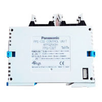
FPG-C32T2HTM
Panasonic FPG-C32T2HTM Logic Controller Manuals
Manuals and User Guides for Panasonic FPG-C32T2HTM Logic Controller. We have
2
Panasonic FPG-C32T2HTM Logic Controller manuals available for free PDF download: User Manual
Panasonic FPG-C32T2HTM User Manual (440 pages)
Brand:
Panasonic
| Category:
Controller
| Size: 39.59 MB
Table of Contents
Table of Contents
3
Before You Start
9
Programming Tool Restrictions
11
When Changing Ladder Program from 12K Type to 32K Type
12
Compatibility with FP0
15
1 Functions and Restrictions of the Unit
17
Features and Functions of the Unit
18
Unit Types
22
FPΣ Control Unit
22
FPΣ Expansion Unit
23
FP0 Expansion Unit
24
Communication Cassette
24
Restrictions on Unit Combinations
25
Restrictions on FP0 Expansion Unit
25
Programming Tools
27
Tools Needed for Programming
27
Software Environment and Suitable Cable
27
2 Specifications and Functions of the Unit
29
Parts and Functions
30
Input and Output Specifications
34
Input Specifications
34
Output Specifications
36
Terminal Layout Diagram
39
Control Unit (for C32)
39
Control Unit (for C28)
40
Control Unit (for C24)
40
Analog Potentiometer
41
Overview of Analog Potentiometer
41
Thermister Input (Only for TM Type)
42
Overview of Thermister Input
42
Loading of Thermister Temperature Data
44
Calendar Timer
45
Area for Clock/Calendar Function
45
Setting of Clock/Calendar Function
45
Example Showing the Clock/Calendar Being Used
46
30-Second Compensation Sample Program
47
3 Expansion
49
Type of Expansion Unit
50
Expansion Method of Units for FP0 and FPΣ
51
Expansion Method of FPΣ Expansion Unit
52
Specifications of FPΣ Expansion Unit
53
FPΣ Expansion Unit
53
FPΣ Expansion Data Memory Unit
57
Other Expansion Units
60
4 I/O Allocation
61
I/O Allocation
62
Allocation of FPΣ Control Unit
63
Allocation of FPΣ Expansion Unit
64
I/O Numbers of FPΣ Expansion Unit
64
Allocation of FP0 Expansion Unit
65
I/O Numbers of FP0 Expansion Unit
65
5 Installation and Wiring
67
Installation
68
Installation Environment and Space
68
Installation Using the Optional Mounting Plate
71
Wiring of Power Supply
74
Grounding
76
Wiring of Input and Output
77
Input Wiring
77
Output Wiring
79
Precautions Regarding Input and Output Wirings
80
Wiring of MIL Connector Type
81
Wiring of Terminal Block Type
83
Safety Measures
85
Momentary Power Failures
85
Protection of Power Supply and Output Sections
86
Installation and Setting of Backup Battery
87
Installation of Backup Battery
87
System Register Setting
88
Time for Replacement of Backup Battery
88
Lifetime of Backup Battery
89
6 High-Speed Counter, Pulse Output and PWM Output Functions
91
Overview of each Functions
92
Three Functions that Use Built-In High-Speed Counter
92
Performance of Built-In High-Speed Counter
93
Specifications
94
Functions Used and Restrictions
96
Booting Time
99
High-Speed Counter Function
100
Overview of High-Speed Counter Function
100
Input Modes and Count
100
Minimum Input Pulse Width
101
I/O Allocation
102
Instructions Used with High-Speed Counter Function
102
Sample Program
105
Pulse Output Function
108
Overview of Pulse Output Function
108
Types of Pulse Output Method and Operation Modes
109
I/O Allocation
111
Pulse Output Control Instructions (F0) (F1)
112
Positioning Control Instruction F171 - Trapezoidal Control (Common to Transistor Type)
115
Positioning Control Instruction F171 - Home Return (Common to Transistor Type)
120
Pulse Output Instruction F172 - JOG Operation (Common to Transistor Type)
126
Positioning Control Instruction F174 - Data Table Contro
130
Action of the Flag Concerning Linear Interpolation and Circular Interpolation
132
Pulse Output Instruction F175 - Linear Interpolation (Only for C32T2, C28P2, C32T2H and C28P2H)
138
Pulse Output Instruction F176 - Circular Interpolation (Only for C32T2, C28P2, C32T2H and C28P2H)
140
PWM Output Function
149
Overview
149
PWM Output Instruction F173
149
7 Communication Cassette
151
Functions and Types
152
Functions of Communication Cassette
152
Types of Communication Cassette
156
Names and Principle Applications of the Ports
159
Setting of AFPG806 Switch
159
Communication Specifications
160
Precaution When Using RS485 Port
162
Installation and Wiring
164
Installation of Communication Cassette
164
Wiring
165
Cables
167
Communication Function 1: Computer Link
168
Computer Link
168
1:1 Communication (Computer Link)
176
1:N Communication (Computer Link)
179
MEWTOCOL Master (Sample Program) (Available for 32K Type Only)
184
Communication Function: General-Purpose Serial Communication
186
General-Purpose Serial Communication
186
Communication with External Devices
189
Connection with 1:1 Communication (General-Purpose Serial Communication)
199
1:N Communication (General-Purpose Serial Communication)
211
Communication Function 3: PC(PLC) Link
212
PC(PLC) Link
212
Setting Communication Parameters
214
Monitoring
223
Connection Example of PC(PLC) Link
224
PC(PLC) Link Response Time
228
Communication Function 4: MODBUS RTU Communication
232
MODBUS RTU Communication
232
8 Self-Diagnostic and Troubleshooting
239
Self-Diagnostic Function
240
LED Display for Status Condition
240
Operation on Error
240
Troubleshooting
241
If ERROR/ALARM LED Is Flashing
241
If ERROR/ALARM LED Is on
242
ALL Leds Are off
243
Diagnosing Output Malfunction
244
A Protect Error Message Appears
245
PROG Mode Does Not Change to RUN
245
A Transmission Error Has Occurred through RS485
246
No Communication Is Available through RS232C
246
9 Precautions During Programming
249
Use of Duplicated Output
250
Duplicated Output
250
When Output Is Repeated with an OT, KP, SET or RST Instruction
250
Handling BCD Data
252
BCD Data
252
Handling BCD Data in the PLC
252
Handling Index Registers
253
Index Registers
253
Memory Areas Which Can be Modified with Index Registers
253
Example of Using an Index Register
254
Operation Errors
255
Outline of Operation Errors
255
Operation Mode When an Operation Error Occurs
255
Dealing with Operation Errors
255
Points to Check in Program
256
Instruction of Leading Edge Detection Method
257
Instructions of Leading Edge Detection Method
257
Operation and Precautions When RUN Starts
258
Precautions When Using a Control Instruction
259
Precautions for Programming
261
Rewrite Function During RUN
262
Operation of Rewrite During RUN
262
Cases Where Rewriting During Run Is Not Possible
263
Procedures and Operation of Rewrite During RUN
265
Processing During Forced Input and Output
267
Processing When Forced Input/Output Is Initiated During RUN
267
10 Specifications
269
Table of Specifications
270
General Specifications
270
Performance Specifications
273
I/O No. Allocation
280
Relays, Memory Areas and Constants
282
11 Dimensions
287
Dimensions
288
Control Unit (Transistor Output Type)
288
Control Unit (Relay Output Type)
289
Expansion Unit
290
Connection Diagram with Motor Driver
291
Matsushita Electric Industrial Co., Ltd. MINAS A-Series, AIII-Series
291
Matsushita Electric Industrial Co., Ltd. MINAS Sseries, E-Series
291
Power Supply Specification
292
12 Appendix
293
System Registers / Special Internal Relays / Special Data Registers
295
Table of System Registers for FPΣ
298
Table of Special Internal Relays for FPΣ
304
Table of Special Data Registers for FPΣ
313
Table of Basic Instructions
327
Table of High-Level Instructions
361
Table of Error Codes
421
MEWTOCOL-COM Communication Commands
435
Hexadecimal/Binary/Bcd
436
ASCII Codes
437
Advertisement
Panasonic FPG-C32T2HTM User Manual (332 pages)
Brand:
Panasonic
| Category:
Controller
| Size: 25.4 MB
Table of Contents
Table of Contents
8
1 Safety Measures
18
Safety Measures
19
2 Overview
22
Features
23
Unit Types
26
Cpu
26
FPΣ Expansion Units
26
Communication Cassettes
26
Units for FP0 and FPΣ
27
Accessories
27
Restrictions on Unit Combinations
28
FP0 Expansion Units
28
FPΣ Expansion Units
29
Programming Tools
30
FP0 Program Compatibility
31
3 CPU Types
32
Parts and Functions
33
Input and Output Specifications
37
Input Specifications
37
Output Specifications
39
Terminal Layout
43
C32 Cpu
43
C28 Cpu
44
C24 Cpu
45
Analog Potentiometer
46
Thermistor Input Functions
48
Loading Thermistor Temperature Data
49
Clock/Calendar Function
52
Memory Area for Clock/Calendar Function
52
Settings for Clock/Calendar Function
52
Sample Program for Fixed Schedule and Automatic Start
54
Sample Program for 30-Second Compensation
54
4 Expansion
58
Expansion Methods
59
FPΣ I/O Expansion Units
60
Parts and Functions
60
Input and Output Specifications
61
Terminal Layout
64
FPΣ Memory Expansion Unit
65
Data Organization
66
Accessing the Memory Expansion Unit
67
F150_READ Instruction
68
F151_WRT Instruction
69
Battery Error
70
Other FPΣ Expansion Units
71
Communication Cassettes
72
5 I/O Allocation
74
General
75
Fpσ Cpu
77
FPΣ Expansion Units
78
FP0 Expansion Units
79
6 Installation and Wiring
82
Installation
83
Installation Environment and Space
83
Using DIN Rails
85
Using Optional Mounting Plates
86
Slim Type and FPΣ Mounting Plates
86
Flat Type Mounting Plate
88
Connecting FPΣ Expansion Units
90
Connecting FP0 Expansion Units
91
Installing Communication Cassettes
92
Safety Instructions for Wiring
93
Wiring the Power Supply
95
Grounding
97
Input and Output Wiring
99
Input Wiring
99
Output Wiring
102
Protective Circuit for Capacitive Loads
103
Protective Circuit for Inductive Loads
103
Wiring the MIL Connector
105
Wiring the Terminal Block
107
Wiring the Communication Cassette
109
Transmission Cables
111
Backup Battery
112
Installing the Backup Battery
113
Setting the Battery Error Alarm
113
Specifying Hold Areas
114
Lifetime of the Backup Battery
114
7 High-Speed Counter and Pulse Output
116
Overview
117
Function Specifications and Restrictions
119
High-Speed Counter Function
119
Pulse Output Function
120
PWM Output Function
121
Restrictions
122
Booting Time
123
High-Speed Counter Function
124
Count Input Modes
124
Minimum Input Pulse Width
126
I/O Allocation
126
Instructions and System Variables
127
Writing the High-Speed Counter Control Code
128
Writing and Reading the Elapsed Value for the High-Speed Counter
130
F166_Highspeedcounter_Set, Target Value Match on
131
F167_Highspeedcounter_Reset, Target Value Match off
132
Sample Programs
132
Positioning Operations with a Single-Speed Inverter
133
Positioning Operations with a Double-Speed Inverter
135
Pulse Output Function
137
Pulse Output Methods and Position Control Modes
137
I/O Allocation
140
Instructions and System Variables
141
Writing the Pulse Output Control Code
143
Writing and Reading the Elapsed Value of the Pulse Output
145
F171_Pulseoutput_Home, Home Return
146
F171_Pulseoutput_Trapezoidal, Trapezoidal Control
146
F172_Pulseoutput_Jog, JOG Operation
148
F174_Pulseoutput_Datatable, Data Table Control
149
F175_Pulseoutput_Linear, Linear Interpolation
150
F176_Pulseoutput_Center, Circular Interpolation (Center Position)
151
F176_Pulseoutput_Pass, Circular Interpolation (Pass Position)
152
Sample Programs
153
Example 1: Trapezoidal Control
156
Example 2: Home Return in a Backward Direction
159
Example 3: Home Return in a Forward Direction (+)
160
Example 4: Home Return in a Backward Direction (-) with 2 Axes
162
Example 5: JOG Operation
165
Example 6: Linear and Circular Interpolation Control
165
Example 7: Circular Interpolation, Continue Mode
166
PWM Output Function
168
8 Communication
170
Communication Modes
171
Terminology in FPWIN Pro and FPWIN GR
171
Ports: Names and Principle Applications
172
MEWTOCOL-COM Master/Slave
172
Program Controlled Communication
173
PLC Link
174
Modbus RTU Master/Slave
175
Communication Cassettes
176
Communication Status Leds
176
FPG-COM1: 1-Channel RS232C Type
176
FPG-COM2: 2-Channel RS232C Type
177
FPG-COM3: 1-Channel RS485 Type
177
FPG-COM4: 1-Channel RS485 and 1-Channel RS232C Combination Type
178
DIP Switch Setting on FPG-COM4
179
Difference of Dimensions
179
Communication Specifications
180
Communication Parameters
182
Setting System Registers in PROG Mode
182
Setting Station Numbers
184
Changing Communication Mode in RUN Mode
186
Adjusting the Response Time
186
Mewtocol-Com
188
Operation Outline for MEWTOCOL-COM Slave
190
Command and Response Format
191
Commands
193
Setting Communication Parameters
194
1:1 Slave Communication
194
1:1 Communication with Computer
195
1:1 Communication with Programmable Displays of GT Series
197
1:N Slave Communication
199
Wiring
201
Sample Program for Master Communication
202
Program Controlled Communication
204
Setting Communication Parameters
205
Sending Data to External Devices
206
Receiving Data from External Devices
210
Data Format
214
Flag Operation in Program Controlled Communication
215
Start Code: No-STX; End Code: CR
217
Start Code: STX; End Code: ETX
218
1:1 Communication
220
1:1 Communication with Micro-Imagechecker
221
1:1 Communication with FP Series PLC
228
1:N Communication
238
PLC Link
240
Setting Communication Parameters
241
Link Area Allocation
242
Example for PLC Link 0
244
Example for PLC Link 1
245
Partial Use of Link Areas
246
Precautions for Allocating Link Areas
248
PLC Link 0 and 1 Allocation Setting
249
Setting the Highest Station Number for a PLC Link
249
Monitoring
250
Connection Example
252
PLC Link Response Time
256
Reducing Transmission Cycle Times
259
Error Detection Time for Transmission Assurance Relays
260
Modbus RTU Communication
261
Sample Program for Master Communication
264
Setting Communication Parameters
264
9 Security Functions
266
Security Function Types
267
Security Settings in FPWIN Pro
268
Upload Protection
268
PLC Protection (Password Protection)
269
FP Memory Loader
270
Upload Protection
270
Download Protection
271
10 Other Functions
274
F-ROM Backup (P13_EPWT)
275
Sampling Trace
276
11 Troubleshooting
278
LED Display for Status Condition
279
Operation on Error
280
ERROR/ALARM LED Is Flashing
281
ERROR/ALARM LED Is on
282
All Leds Are off
283
Diagnosing Output Malfunction
284
Password Protection Error Message
285
PROG Mode Does Not Change to RUN
286
No RS485 Communication
287
No RS232C Communication
288
12 Appendix
290
General Specifications
291
Weight
292
Current Consumption
292
Performance Specifications
294
High-Speed Counter, Pulse Output and PWM Output Specifications
296
Maximum Counting Speed and Output Frequency
297
Communication Specifications
299
I/O Allocation
301
Dimensions
303
Transistor Output Type CPU
303
Relay Output Type CPU
304
Expansion Unit
305
Communication Cassettes
306
Relays and Memory Areas
307
System Registers
309
Precautions When Setting System Registers
309
Types of System Registers
309
Checking and Changing System Registers
310
Table of System Registers
310
Error Codes
316
Error Codes E1 to E8
316
Self-Diagnostic Error Codes
317
MEWTOCOL-COM Error Codes
318
MEWTOCOL-COM Communication Commands
320
Data Types
321
Hexadecimal/Binary/Bcd
322
ASCII Codes
323
13 Index
324
Advertisement
Related Products
Panasonic FPG-C32T2H
Panasonic FPG-C32T2
Panasonic FPG-C32T
Panasonic FPG-C32T2TM
Panasonic FPG-C32TH
Panasonic FPG-C32THTM
Panasonic FPG-C32T2H-A
Panasonic FPG-C28P2H
Panasonic FPG-C28P2HTM
Panasonic FPG-COM3
Panasonic Categories
Camcorder
Air Conditioner
TV
Digital Camera
Cordless Telephone
More Panasonic Manuals
Login
Sign In
OR
Sign in with Facebook
Sign in with Google
Upload manual
Upload from disk
Upload from URL