Sign In
Upload
Manuals
Brands
Panasonic Manuals
VCR
AJSD955AP
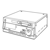
Panasonic AJSD955AP Manuals
Manuals and User Guides for Panasonic AJSD955AP. We have
2
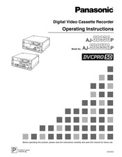
Panasonic AJSD955AP manuals available for free PDF download: Service Manual, Operating Instructions Manual
Panasonic AJSD955AP Service Manual (562 pages)
Brand:
Panasonic
| Category:
Cassette Player
| Size: 48.67 MB
Table of Contents
English
9
Table of Contents
9
Servicing Fixtures & Tools
10
Alignment Tape
12
Vfm3580Km / L (Ntsc)
12
VFM3010EDS / L (NTSC) (DV Adjustment Tape)
13
VFM3000EDS / L (DV (LISTA) Adjustment Tape)
14
VFM3680KM / L (PAL) (25 M Adjustment Tape)
14
List of Recommended Measuring Instruments
14
Maintenance
15
Maintenance Schedule
15
Layout of the Maintenance Parts
16
MANUAL TAPE EJECT (Emergency Eject)
17
A/C Head Cleaning Method:(Weekly)
18
Post Cleaning Method:(Weekly)
18
Pinch Roller and Capstan Shaft Cleaning Method:(Weekly)
18
Cylinder Lead Cleaning Method:(Weekly)
18
Cylinder Head Cleaning Method:(Daily)
18
Cleaning Method
18
Software Version Display
19
Software & Pld Version
20
Software Version & Check Sum
20
Error Rate Display
21
Hour Meter Display
23
Tp & Main Signal for Tape Path Confirmation
24
Internal Switch Setting Method
26
Software Version Upgrade Method
27
Microcomputer (FLASH) /PLD Chart
27
Flash ROM Software Version up Procedure
28
PLD Version Upgrade Procedure
34
Service Menu
41
Service Menu Operation Method
41
DEFAULT Operation
42
Service Menu Contents
43
Error Messages
65
Appendix
68
FLASH ROM VERSION up PROCEDURE for I/F ROM Using Flash Memory Version up Tool (VFK1304A)
69
Circuit Board Layout Drawing
72
Disassembly Procedures
74
Removal of Top Panel
74
Removal of Bottom Panel
74
Removal of Front Panel Unit
74
Removal of Front Loading Unit
74
Removal of Mechanism Unit
75
Removal of Cylinder Unit
76
Removal of Power Supply Unit
76
Removal of Fan Motor
77
Name of Tape Transportation
80
Table of Test Point
81
Table of Test Point, VR, Setting for Service Menu
81
Tension Sensor Voltage Adjustment (1)
82
Tension Sensor Voltage Adjustment (2)
82
Mechanical Adjustment Procedures
82
Tension Arm Adjustment Flowchart
82
Post Height Pre-Adjustment
82
Tension Arm PLAY and REV Voltage Confirmation
84
Tension Regulator Spring Adjustment
84
REV Tension Confirmation
85
Tension Confirmation
86
Photo Sensor Voltage Adjustment
87
Tape Path Adjustment Procedure
88
Envelope Waveform Adjustment
89
Post Limit Confirmation (PLAY)
89
A/C Head Adjustment Method (General)
90
A/C Head Tilt Adjustment
92
A/C Head Height Adjustment
92
A/C Head Height Confirmation
93
A/C Head Tilt Confirmation
93
A/C Head Azimuth and X-Value Adjustment
94
Compensation Adjustment of X Value
95
REV Tape Path Confirmation and Adjustment (T4 Post Height Adjustment)
95
CTL Self Recording Level Confirmation
96
Play Tape Path Limit Confirmation
96
Confirmation of Envelope on REV, REW and FF Mode
97
Confirmation of Play Start Envelope
97
REV Mode Tape Path Limit Confirmation
98
FF, REW Mode Tape Path Limit Confirmation
98
Screw Lock Tight of A/C Head and T3, T4 Post
98
Confirmation of Tape Damage for Long Tape Playback
99
LISTA Adjustment Procedure
100
LISTA Connection and Boot up
101
How to Enter the Attachment Data of Alignment Tape
103
RP Head Sensitivity Adjustment and Sensitivity Detection (25M Mode)
104
LISTA Linearity Adjustment and Waving Measurement (25M Mode)
106
PB Head LISTA Sensitivity Adjustment and Sensitivity Detection (25M Mode)
108
RP Head Sensitivity Adjustment and Sensitivity Detection (50M Mode)
110
LISTA Linearity Adjustment and Waving Measurement (50M Mode)
112
PB Head LISTA Sensitivity Adjustment and Sensitivity Detection (50M Mode)
114
RP HEAD (for DV) Lista Sensitivity Adjustment
116
Self-REC/PLAY Envelope Waveform Confirmation
118
Tape Loading Method
118
Major Mechanical Parts Replacement & Adjustment Procedures
119
Cylinder Unit Replacement
119
Cleaning Arm Unit Replacement
120
T1 Guide Position Adjustment
120
Adjustment Flow Chart after Cylinder Unit Replacement
121
Supply & Take-Up Reel Rotor Unit Replacement
122
Main Brake Torque Confirmation
123
Supply & Take-Up Brake Arm Unit Replacement
123
Supply Brake Solenoid Replacement and Adjustment
123
Take-Up Brake Solenoid Replacement and Adjustment
124
Pinch Solenoid Replacement
125
Pinch Solenoid Position Adjustment
125
Pinch Arm Unit Replacement
126
Loading Motor Replacement
126
Mode SW Unit Replacement
127
Main Cam Gear Replacement
127
Thrust Screw Replacement and Adjustment
128
S5 Post Base Unit Replacement
128
Tension Arm Unit Replacement
129
S1 Post Loading Arm Unit Replacement & Adjustment
130
T1 Boat Unit Replacement and Adjustment
131
A/C Head Replacement & Adjustment
133
Cleaner Solenoid Replacement & Adjustment
134
Distinction SW Unit Replacement
136
Reel Drive Motor Unit Replacement
136
Slide Rod Unit Replacement & Adjustment
137
L-M Release Angle Unit Replacement
137
M-Stopper Solenoid Replacement & Adjustment
138
T4 Post Position Adjustment
139
Connector Location
139
Mech. I/F P.C. Board
139
Servo (F7)
142
SERVO FG Offset Adjustment
142
Power Supply Voltage Adjustment
142
Power Supply Unit
142
Reel Torque Gain Adjustment
143
Motor Torque Offset Adjustment
143
Tension Sensor Voltage Adjustment (1)
144
Tension Sensor Voltage Adjustment (2)
144
PG Shifter Adjustment (50M)
145
PG Shifter Adjustment (25M)
145
Rf/Eq (F8)
146
Automatic Adjustment Procedure
146
Manual Adjustment Procedure
153
Adjustment Data Initialization
154
VCO Center Frequency Value Reading
154
Envelope Level Adjustment
155
Phase Compensation Adjustment, Confirmation of Error Rate and AEQ Tap Coefficient Values Setting
156
REC Frequency Characteristic Setting, REC Current Adjustment, Confirmation of Error Rate
160
Storing Adjustment Data
161
Out (F5)
162
Connection
162
Reference CF Detection Adjustment (1)
163
Reference PLL Center Frequency Adjustment (1)
163
Composite Sync DC Level Adjustment
164
Composite y Level Adjustment
164
Composite Frequency Characteristic Adjustment
164
Composite YC Gain & Delay Adjustment
165
Composite SCH Adjustment (1)
165
System Sub-Carrier Phase Adjustment (1)
165
Component Frequency Characteristic Adjustment
166
Component Sync DC Adjustment
166
Component y Level Adjustment
166
Component Pb Level Adjustment
167
Component Pr Level Adjustment
167
Component Y-Pb Timing Adjustment
168
Component Y-Pr Timing Adjustment
168
Component Pb Frequency Characteristic Adjustment
169
Component Pr Frequency Characteristic Adjustment
169
Reference PLL Centerfrequency Adjustment (2)
170
Reference CF Detection Adjustment (2)
170
Composite SCH Adjustment(2)
171
System Sub-Carrier Phase Adjustment (2)
171
In (F2A:aj-Ya931G)
172
Connection and Menu Setting
173
PLL DC Adjustment
173
Composite SCH Detection Adjustment
174
Composite Color Demodulation Timing Adjustment
174
Component y Signal Level Adjustment
175
Component y Signal Offset Level Adjustment
175
Component Pb Signal Offset Level Adjustment
176
Component Pr Signal Offset Level Adjustment
176
Component Pb Signal Level Adjustment
177
Component Pr Signal Level Adjustment
177
Component Pb Signal Timing Adjustment
178
Component Pr Signal Timing Adjustment
178
Composite y Signal Level Adjustment
179
Composite y Signal Offset Level Adjustment
179
Composite Pb Signal Offset Level Adjustment
180
Composite Pr Signal Offset Level Adjustment
180
Composite Pb Signal Level Adjustment
181
Composite Pr Signal Level Adjustment
181
Composite Pb/Pr Signal Timing Adjustment
182
Composite Video out Phase Adjustment
183
Composite Vector Adjustment
183
In (F2A:aj-Ya932G)
184
Connection and Menu Setting
185
PLL DC Adjustment
186
Composite Color Demodulation Timing Adjustment
186
Composite SCH Detection Adjustment
186
Component y Signal Level Adjustment
187
Component y Signal Offset Level Adjustment
187
Component Pb Signal Offset Level Adjustment
188
Component Pr Signal Offset Level Adjustment
188
Component Pb Signal Level Adjustment
189
Component Pr Signal Level Adjustment
189
Component Pb Signal Timing Adjustment
190
Component Pr Signal Timing Adjustment
190
Composite y Signal Level Adjustment
191
Composite y Signal Offset Level Adjustment
191
Composite Pb Signal Offset Level Adjustment
192
Composite Pr Signal Offset Level Adjustment
192
Composite Pb Signal Level Adjustment
193
Composite Pr Signal Level Adjustment
193
Composite Pb/Pr Signal Timing Adjustment
194
Composite Video out Phase Adjustment
195
Composite Vector Adjustment
195
Rec/Pb (F4)
196
Setting
196
V-BLK TELETEXT OFFSET LEVEL Adjustment
196
V-BLK TELETEXT LEVEL Adjustment
196
Audio (F1) & Rf/Cue
197
Setting and VR Location
197
CH1-4 Output Level Adjustment
198
CH1-4 Input Level Adjustment
198
REC VR Center Adjustment
198
CUE REC/PB Level Adjustment
199
CUE PB Level Adjustment
199
CUE BIAS CURRENT Adjustment
199
CUE Noise Cancel Adjustment
200
TP, VR and SW Location
201
F1: Audio P.C.board (Vep84383A)
201
F2B:a_Proc P.C.board (Vep84384A)
202
F3A:sdi P.C.board (Vep83605A)
202
F4: Rec Pb P.C.board (Vep83596B/C)
203
F5: V_Out P.C.board (Vep83597B/C)
204
F6: Syscon P.C.board (Vep86326B/C)
204
F7: Servo P.C.board (Vep82246B/C)
205
F8: Rf/Eq P.C.board (Vep85207A)
205
Rf/Cue P.C.board (Vep85208A)
205
F3B:sdti P.C.board (Vep83595A)(Aj-Yac930G:option)
206
Block Diagrams
207
Overall Block Diagram
208
F1: Audio Block Diagram
209
F2A: V_In Block Diagram (Aj-Ya931G, Aj-Ya932G: Option)
210
F2B: a Proc Block Diagram
211
F3A: Sdi (1394) Block Diagram
212
F4: Rec_Pb Block Diagram
213
F5: V_Out Block Diagram
214
F6: Syscon Block Diagram
215
F7: Servo Block Diagram
216
F8: Rf/Cue, Rf/Eq Block Diagram
217
Front Block Diagram
218
F3B: Sdti Block Diagram (Aj-Yac930G: Option)
219
F3A: Sdi P.C.board (Vep83605A)
427
Rf/Cue P.C.board (Vep85208A)
439
Power1 P.C.board (Vep81221C)
445
Mecha_If P.C.board (Vep82239A)
447
Eject P.C.board (Vep80C42A)
448
Front Sub P.C.board (Vep80C43A)
448
Mecha_If2 P.C.board (Vep82247A)
448
Servicing Fixtures & Tools
455
Mechanical Chassis Assembly (1)
456
Mechanical Chassis Assembly (2)
458
Sub Chassis Assembly
460
Cassette Compartment Assembly
462
Casing Parts Assembly
464
Front Panel Assembly
466
Chassis Frame Assembly
468
Rear Panel Assembly
470
Packing Parts Assembly
472
Packing Parts Assembly (Aj-Ya931G, Ya932G/Aj-Yac930G)
474
Electrical Replacement Parts List (Aj-Sd930P)
476
Electrical Replacement Parts List (Aj-Sd955Ap)
514
Electrical Replacement Parts List (Aj-Ya931G)
552
Electrical Replacement Parts List (Aj-Ya932G)
557
Electrical Replacement Parts List (Aj-Yac930G)
562
Advertisement
Panasonic AJSD955AP Operating Instructions Manual (81 pages)
Brand:
Panasonic
| Category:
VCR
| Size: 1.11 MB
Table of Contents
Table of Contents
3
Introduction
3
Features
4
Parts and Their Functions
5
Front Panel
5
Display Panel
11
Rear Panel
13
Connections
15
Tapes
17
Jog/Shuttle
18
Manual Editing SD955A
19
Sd955A
19
Automatic Editing (Deck-To-Deck)
20
Sd955A
20
Switch Settings and Adjustments
20
Selecting the Editing Mode
21
Registering the Edit Points
21
Checking and Previewing Edit Points
22
Modifying Edit Points
23
Executing and Reviewing Automatic Editing
24
Audio Split Editing
25
Sd955A
25
Variable Memory Editing
27
Sd955A
27
Setup (Initial Settings)
28
Setup Menus
29
SYSTEM Menu
32
Basic
34
USER Menus
35
Operation
36
Interface
39
Edit
40
Tape Protect
42
Time Code
43
Video
45
Audio
48
Blank
51
Menu
54
Time Code/User's Bit
55
Superimpose Screen
57
Video Output Signals and Servo Reference Signal
58
Audio V Fade Function
60
Audio Recording Channel and Monitor Output Selection
61
Printed Circuit Board
61
Rack Mounting
62
Video Head Cleaning
63
Condensation
63
Maintenance
63
Error Messages
64
RS-232C Interface
69
SDTI Interface
74
Connector Signals
75
Specifications
77
Advertisement
Related Products
Panasonic AJSD955BP - DVC PRO50 DECK
Panasonic AJSD955A - DVC PRO CAMCORDER
Panasonic AJ-SD955BE
Panasonic AJ-SD955
Panasonic AJ-SD955E
Panasonic AJSD930B - DVCPRO 50 DECK
Panasonic AJ-SD93E
Panasonic AJ-SD93P
Panasonic AJ-SD965p
Panasonic AJ-SD930
Panasonic Categories
Camcorder
Air Conditioner
TV
Digital Camera
Cordless Telephone
More Panasonic Manuals
Login
Sign In
OR
Sign in with Facebook
Sign in with Google
Upload manual
Upload from disk
Upload from URL