Sign In
Upload
Manuals
Brands
Motorola Manuals
Motherboard
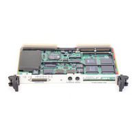
MVME2604-2141A
Motorola MVME2604-2141A Manuals
Manuals and User Guides for Motorola MVME2604-2141A. We have
2
Motorola MVME2604-2141A manuals available for free PDF download: Installation And Use Manual
Motorola MVME2604-2141A Installation And Use Manual (210 pages)
MVME2600 Series
Brand:
Motorola
| Category:
Motherboard
| Size: 1.2 MB
Table of Contents
Table of Contents
7
Introduction
18
Figure 1-1. MVME2603/2604 Base Board Block
18
Equipment Required
19
Table 1-1. Vmemodule/Transition Module Correspondence
19
Overview of Startup Procedure
20
Table 1-2. Startup Overview
20
Unpacking Instructions
21
Hardware Conþguration
21
MVME2603/2604 Base Board Preparation
22
Cache Mode Control (J3)
23
Flash Bank Selection (J10)
23
Figure 1-2. MVME2603/2604 Switches, Headers, Connectors, Fuses
26
Serial Port 4 Transmit Clock Receiver Buffer Control (J20)
28
System Controller Selection (J22)
30
Remote Status and Control
30
MVME712M Transition Module Preparation
31
Figure 1-3. MVME712M Connector and Header Locations
32
Figure 1-4. J15 Clock Line
33
Serial Port 4 Clock Conþguration
33
Serial Ports 1-4 DCE/DTE Conþguration
33
Table 1-3. MVME712M Port/Jumper Correspondence
33
Chapter 1 Hardware Preparation and Installation
35
Figure 1-7. MVME712M Serial Port 3 DCE
36
Figure 1-9. MVME712M Serial Port 4 DCE
38
Figure 1-10. MVME712M Serial Port 4 DTE
39
Figure 1-11. MVME712M P2 Adapter Component Placement
40
P2 Adapter Preparation
40
MVME761 Transition Module Preparation
41
Figure 1-12. MVME761 Connector and Header
42
Serial Ports 1 and 2
43
Figure 1-13. MVME761 Serial Ports 1 and 2 (DCE Only)
45
Figure 1-14. MVME761 Serial Ports 3 and 4 DCE
46
P2 Adapter Preparation (Three-Row)
48
Figure 1-16. MVME761 P2 Adapter (Three-Row) Component Placement
49
Figure 1-17. MVME761 P2 Adapter (Five-Row) Component
50
P2 Adapter Preparation (Five-Row)
50
Hardware Installation
51
ESD Precautions
51
RAM200 Memory Mezzanine Installation
52
Figure 1-18. RAM200 Placement on MVME2603/2604
53
PMC Module Installation
54
Figure 1-19. PMC Module Placement on
55
PMC Carrier Board Installation
56
Figure 1-20. PMC Carrier Board Placement on MVME2603/2604
57
MVME2603/2604 Vmemodule Installation
58
MVME712M Transition Module Installation
60
Figure 1-21. MVME712M/MVME2603/2604 Cable Connections
63
Hardware Preparation and Installation
63
MVME761 Transition Module Installation
64
Figure 1-22. MVME761/MVME2603/2604 Cable Connections
65
System Considerations
66
MVME2603/2604 Vmemodule
68
Chapter 2 Operating Instructions
71
Introduction
71
Applying Power
71
ABORT Switch (S1)
72
Figure 2-1. Ppcbug System
72
RESET Switch (S2)
73
Front Panel Indicators (DS1 - DS6)
74
Memory Maps
75
Processor Memory Map
75
Default Processor Memory Map
75
PCI Local Bus Memory Map
76
Table 2-1. Processor Default View of the Memory Map
76
Vmebus Memory Map
77
Programming Considerations
77
Figure 2-2. Vmebus Master Mapping
78
PCI Arbitration
79
Table 2-2. PCI Arbitration Assignments
79
Interrupt Handling
80
Figure 2-3. MVME2603/MVME2604 Interrupt Architecture
81
DMA Channels
82
Sources of Reset
82
Table 2-3. IBC DMA Channel Assignments
82
Endian Issues
83
Table 2-4. Classes of Reset and Effectiveness
83
PCI Domain
84
Processor/Memory Domain
84
Vmebus Domain
85
Chapter 3 Functional Description
87
General Description
89
Block Diagram
91
Figure 3-1. MVME2603/2604 Block Diagram
91
SCSI Interface
92
SCSI Termination
92
Ethernet Interface
93
PCI Mezzanine Interface
94
ISA Super I/O Device (ISASIO)
95
Asynchronous Serial Ports
97
Parallel Port
97
Disk Drive Controller
98
Keyboard and Mouse Interface
98
Vmebus Interface
95
PCI-ISA Bridge (PIB) Controller
98
Real-Time Clock/Nvram/Timer Function
99
Programmable Timers
100
Interval Timers
100
16-Bit Timers
101
Serial Communications Interface
101
Z8536 CIO Device
102
Base Module Feature Register
102
P2 Signal Multiplexing
103
ABORT Switch (S1)
104
Table 3-2. P2 Multiplexing Sequence
104
Front Panel Indicators (DS1 - DS6)
105
RESET Switch (S2)
105
Polyswitches (Resettable Fuses)
106
I/O Power
106
Table 3-3. Fuse Assignments
106
PM603/604 Processor
107
Flash Memory
108
Speaker Control
107
MVME712M Transition Module
109
RAM200 Memory Module
109
MVME761 Transition Module
110
Serial Interface Modules
111
Chapter 4 Connector Pin Assignments
113
Common Connectors
115
LED Mezzanine Connector J1
115
Debug Connector J2
115
Table 4-1. LED Mezzanine Connector
115
Table 4-2. Debug Connector
116
Floppy/Led Connector J4
119
Table 4-3. Floppy/Led Connector
119
PCI Expansion Connector J5
120
Table 4-4. PCI Expansion Connector
120
Keyboard and Mouse Connectors J6, J8
122
DRAM Mezzanine Connector J7
122
Table 4-5. Keyboard Connector
122
Table 4-6. Mouse Connector
122
Table 4-7. DRAM Mezzanine Connector
123
PCI Mezzanine Card Connectors
125
Table 4-8. PCI Mezzanine Card Connector
126
Vmebus Connector P1
127
Table 4-8. PCI Mezzanine Card Connector (Continued)
127
Table 4-9. Vmebus Connector P1
128
MVME712M-Compatible Versions
129
Vmebus Connector P2 (MVME712M I/O Mode)
129
SCSI Connector (MVME712M I/O Mode)
129
Table 4-10. Vmebus Connector P2 (MVME712M I/O Mode)
130
Table 4-11. SCSI Connector (MVME712M)
131
Serial Ports 1-4 (MVME712M I/O Mode)
132
Parallel Connector (MVME712M I/O Mode)
133
Table 4-13. Parallel I/O Connector (MVME712M)
133
Ethernet AUI Connector
134
Table 4-14. Ethernet AUI Connector (MVME712M)
134
MVME761-Compatible Versions
135
Vmebus Connector P2 (MVME761 I/O Mode)
135
Table 4-15. Vmebus Connector P2 (MVME761 I/O Mode)
136
Serial Ports 1 and 2 (MVME761 I/O Mode)
137
Serial Ports 3 and 4 (MVME761 I/O Mode)
138
Parallel Connector (MVME761 I/O Mode)
139
Table 4-18. Parallel I/O Connector (MVME761)
139
Ethernet 10Base-T/100Base-TX Connector
140
Table 4-19. Ethernet 10Base-T/100Base-TX Connector (MVME761)
140
Introduction
87
Features
87
Table 3-1. MVME2603/2604 Features
87
MVME2603/2604 Connectors
113
Chapter 5 Ppcbug
141
Overview
141
Memory Requirements
142
Ppcbug Implementation
142
Using the Debugger
143
Debugger Commands
144
Table 5-1. Debugger Commands
144
Diagnostic Tests
148
Table 5-2. Diagnostic Test
148
Chapter 6 Cnfg and Env Commands
149
ENV - Set Environment
151
Conþguring the Ppcbug Parameters
151
Conþguring the Vmebus Interface
160
Motorola Computer Group Documents
165
Table A-1. Motorola Computer Group Documents
165
Manufacturersõ Documents
166
Related Speciþcations
170
Appendix B Specifications
170
Speciþcations
173
Table B-1. MVME2603/2604
175
Cooling Requirements
176
FCC Compliance
177
Appendix C Serial Interconnections
179
Introduction
179
EIA-232-D Connections
180
Table C-1. EIA-232-D Interconnect
181
Interface Characteristics
182
Table C-2. EIA-232-D Interface Transmitter Characteristics
182
EIA-530 Connections
183
Table C-3. EIA-232-D Interface Receiver Characteristics
183
Table C-4. MVME761 EIA-530 Interconnect Signals
184
Interface Characteristics
186
Table C-5. EIA-530 Interface Transmitter
186
Proper Grounding
187
Table C-6. EIA-530 Interface Receiver
187
Appendix D Troubleshooting CPU Boards: Solving Startup Problems
189
Introduction
189
Table D-1. Troubleshooting MVME2603/2604 Boards
189
Solving Startup Problems
189
Glossary
193
Abbreviations, Acronyms, and Terms to Know
193
Overview
149
Advertisement
Motorola MVME2604-2141A Installation And Use Manual (20 pages)
Brand:
Motorola
| Category:
Single board computers
| Size: 0.12 MB
Advertisement
Related Products
Motorola MVME2604-2021A
Motorola MVME2604-2031A
Motorola MVME2604-2041A
Motorola MVME2604-2091A
Motorola MVME2604-2121A
Motorola MVME2604-2131A
Motorola MVME2604-2191A
Motorola MVME2604-1031A
Motorola MVME2604-1041A
Motorola MVME2604-1121A
Motorola Categories
Cell Phone
Two-Way Radio
Baby Monitor
Cordless Telephone
Radio
More Motorola Manuals
Login
Sign In
OR
Sign in with Facebook
Sign in with Google
Upload manual
Upload from disk
Upload from URL