Sign In
Upload
Manuals
Brands
Motorola Manuals
Single board computers
MVME167-33A
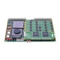
User Manuals: Motorola MVME167-33A Board Computer
Manuals and User Guides for Motorola MVME167-33A Board Computer. We have
1
Motorola MVME167-33A Board Computer manual available for free PDF download: User Manual
Motorola MVME167-33A User Manual (84 pages)
Brand:
Motorola
| Category:
Single board computers
| Size: 3.28 MB
Table of Contents
Table of Contents
4
General Information
12
Introduction
12
Model Designations
12
Table 1-1. MVME167 Model Designations
12
Features
13
Specifications
14
Cooling Requirements
14
FCC Compliance
15
Table 1-2. MVME167 Specifications
15
General Description
16
Equipment Required
17
Related Documentation
18
Support Information
19
Manual Terminology
20
Hardware Preparation and Installation
22
Introduction
22
Unpacking Instructions
22
Hardware Preparation
22
General Purpose Readable Jumpers on Header J1
23
System Controller Header J2
23
Figure 2-1. MVME167 Switches, Headers, Connectors, Fuses, and Leds
24
Serial Port 4 Clock Configuration Select Headers J6 and J7
25
SRAM Backup Power Source Select Header J8
26
Installation Instructions
27
MVME167 Module Installation
27
System Considerations
28
Operating Instructions
30
Introduction
30
Controls and Indicators
30
ABORT Switch S1
30
RESET Switch S2
30
Front Panel Indicators (DS1 - DS4)
30
Memory Maps
32
Local Bus Memory Map
32
Normal Address Range
32
Table 3-1. Local Bus Memory Map
33
Table 3-2. Local I/O Devices Memory Map
34
Detailed I/O Memory Maps
35
Table 3-3. Vmechip2 Memory Map (Sheet 1 of 3)
37
Table 3-4. Pccchip2 Memory Map
43
Table 3-5. Printer Memory Map
45
Table 3-6. MEMC040 Internal Register Memory Map
46
Table 3-7. MCECC Internal Register Memory Map
46
Table 3-8. Cirrus Logic CD2401 Serial Port Memory Map
48
Table 3-9. 82596CA Ethernet LAN Memory Map
52
Table 3-10. 53C710 SCSI Memory Map
53
Table 3-11. MK48T08 BBRAM,TOD Clock Memory Map
54
Table 3-12. BBRAM Configuration Area Memory Map
54
BBRAM,TOD Clock Memory Map
55
Table 3-13. TOD Clock Memory Map
55
Interrupt Acknowledge Map
57
Vmebus Memory Map
57
Vmebus Accesses to the Local Bus
57
Vmebus Short I/O Memory Map
58
Software Initialization
59
Multi-MPU Programming Considerations
59
Local Reset Operation
59
Functional Description
60
Introduction
60
MVME167 Functional Description
60
Data Bus Structure
60
Mc68040 Mpu
61
Eprom
61
Sram
61
Onboard DRAM
62
Battery Backed up RAM and Clock
63
Vmebus Interface
63
I/O Interfaces
63
Serial Port Interface
63
Parallel Port Interface
64
Ethernet Interface
65
SCSI Interface
65
SCSI Termination
66
Local Resources
66
Programmable Tick Timers
66
Watchdog Timer
66
Software-Programmable Hardware Interrupts
66
Local Bus Timeout
66
Timing Performance
67
Local Bus to DRAM Cycle Times
67
ROM Cycle Times
67
SCSI Transfers
67
LAN DMA Transfers
68
Remote Status and Control
68
Figure 4-1. MVME167 Main Module Block Diagram
69
Figure 4-2. Parity DRAM Mezzanine Module Block Diagram
70
Figure 4-3. ECC DRAM Mezzanine Module Block Diagram
71
Introduction
72
Table A-1. EIA-232-D Interconnections
73
Levels of Implementation
74
Signal Adaptations
74
Sample Configurations
75
Figure A-1. Middle-Of-The-Road EIA-232-D Configuration
75
Figure A-2. Minimum EIA-232-D Connection
76
Proper Grounding
77
Advertisement
Advertisement
Related Products
Motorola MVME167-31
Motorola MVME167-32
Motorola MVME167-33
Motorola MVME167-34
Motorola MVME167-31A
Motorola MVME167-32A
Motorola MVME167-34A
Motorola MVME167-03
Motorola MVME167-001A
Motorola MVME167-002A
Motorola Categories
Cell Phone
Two-Way Radio
Baby Monitor
Cordless Telephone
Radio
More Motorola Manuals
Login
Sign In
OR
Sign in with Facebook
Sign in with Google
Upload manual
Upload from disk
Upload from URL