Sign In
Upload
Manuals
Brands
Motorola Manuals
Single board computers
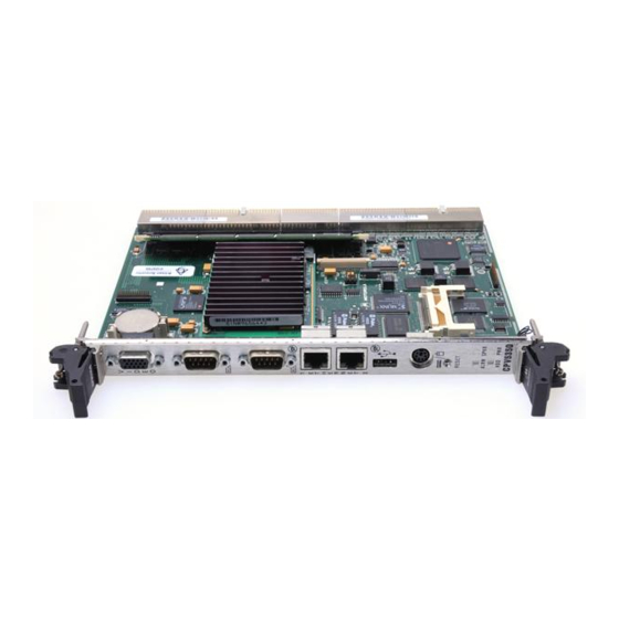
CompactPCI CPV5350
User Manuals: Motorola CompactPCI CPV5350 Computer
Manuals and User Guides for Motorola CompactPCI CPV5350 Computer. We have
1
Motorola CompactPCI CPV5350 Computer manual available for free PDF download: Installation And Reference Manual
Motorola CompactPCI CPV5350 Installation And Reference Manual (87 pages)
Single Board Computer and Transition Module
Brand:
Motorola
| Category:
Single board computers
| Size: 3.6 MB
Table of Contents
Table of Contents
10
CHAPTER 1 CPV5350 Single Board Computer and Transition
16
Introduction
16
Additional Features
16
Input/Output Interfaces
18
Table 1-1. Input/Output Interfaces on the CPV5350 Single Board Computer and
18
Figure 1-1. Block Diagram of the CPV5350 Single Board Computer
20
Special Functions
21
Specifications
22
Table 1-2. Power Requirements for the CPV5350 Single Board Computer
22
Table 1-3. Physical Characteristics of the CPV5350 Single Board Computer
22
Table 1-4. Lithium Battery Specifications
23
Table 1-5. Environmental Specifications
23
CHAPTER 2 Getting Started
24
Antistatic Precautions
24
Before Installing the CPV5350
25
Installing the CPV5350
25
Figure 2-1. Installing the CPV5350 Single Board Computer in Your
27
Powering up the CPV5350
28
Replacing the On-Board Lithium Battery
28
Front Panel Connectors on the CPV5350
31
Figure 2-2. Front Panel Connectors and Leds on the CPV5350 Single Board Computer
32
Rear Panel Connectors on the CPV5350 Transition Module
33
Figure 2-3. Rear Panel Connectors on the CPV5350 Transition Module
34
CHAPTER 3 Components on the CPV5350
36
Components on the CPV5350 Single Board Computer
36
Figure 3-1. Location of Major Components on the CPV5350 Single Board Computer
36
Components for the CPV5350 Transition Module
38
Figure 3-2. Location of Major Components on the CPV5350 TM
39
Table 3-2. List of Board Components for the CPV5350 Transition Module
40
Connecting to and Configuring Connectors
41
CPU Speed Settings
41
CHAPTER 4 Installing Options
42
System Memory Configurations
42
Installing DRAM DIMMS
42
Installing the CPV5350 DIMM
43
Figure 4-1. Inserting a DIMM into a CPV5350 DIMM Socket
43
Installing a Compact FLASH Memory Module
44
Figure 4-2. Compact FLASH Placement on the CPV5350 Single
44
Upgrading the CPU
46
Installing Ethernet Controllers
46
Table A-1. Pin Assignment Locator Table
48
APPENDIX A Pin Assignments
49
Pin Assignments for CPV5350 SBC Front Panel and CPV5350 TM Rear Panel Connectors
49
Table A-2. Front and Rear Panel Connectors on the CPV5350 Single Board Computer (SBC) and CPV5350 Transition Module (TM
49
Keyboard/Mouse PS2 Connectors
50
Table A-3. Keyboard/Mouse P/S2 Connector Pin Assignments for the CPV5350
50
Ethernet Connectors
51
Table A-4. Ethernet Connector Pin Assignments for the CPV5350 Single Board
51
Serial Port Connector
52
Table A-5. Serial Port Connector Pin Assignments for the CPV5350 Single
52
Universal Serial Bus (USB) Connectors
53
Table A-6. USB Connector Pin Assignments for the CPV5350 Single
53
Video Connector
54
Table A-7. Video Connector Pin Assignments for the CPV5350 Single Board
54
Parallel Connector
55
Table A-8. Parallel Connector Pin Assignments for the
55
EIDE Headers
57
Table A-10. EIDE Header Pin Assignments for the
57
Floppy Headers
59
Table A-11. Floppy Header Pin Assignments for the CPV5350 TM
59
Keyboard/Mouse/Power LED Header
61
Table A-12. Keyboard/Mouse/Power LED Header Pin Assignments for the
61
USB Headers
62
Table A-13. USB Header Pin Assignments for the
62
SM Bus and LM78 Header
63
Fan Tachometer Headers
64
Table A-15. Fan Tachometer Header Pin Assignments for the
64
Indicator Led/Miscellaneous Header
65
Table A-16. Indicator Led/Miscellaneous Header Pin Assignments for the CPV5350 Transition Module
65
Pin Assignments for CPV5350 SBC and CPV5350 TM Backplane Connectors
66
CPV5350 Single Board Computer, J5 Connector
67
Table A-17. CPV5350 SBC Backplane Connector (J5) Pin Assignments
67
Table A-18. Signal Descriptions for the CPV5350 Single Board Computer (J5)
68
CPV5350 Single Board Computer, J3 Connector
71
Table A-19. CPV5350 SBC Backplane Connector (J3) Pin Assignments
71
Table A-20. Signal Descriptions for the CPV5350 SBC (J3)
72
CPV5350 Single Board Computer, J4 Local PCI Connector
73
Table A-21. CPV5350 Backplane Connector (J4) Pin Assignments
73
CPV5350 Single Board Computer, J2 Compactpci Bus Connector
74
Table A-22. CPV5350 Backplane Connector (J2) Pin Assignments
74
CPV5350 Single Board Computer, J1 Compact PCI Bus Connector
75
Table A-23. CPV5350 Backplane Connector (J1) Pin Assignments
75
Table A-25. Signal Descriptions for the CPV5350 TM (J5)
77
CPV5350 Transition Module, J3 Connector
80
Table A-26. CPV5350 TM Backplane Connector (J3) Pin Assignments
80
Table A-27. Signal Descriptions for the CPV5350 TM (J3) Backplane Connector
81
APPENDIX B Related Documentation
82
Motorola Computer Group Documents
82
Urls
82
MCG Customer Services
83
Advertisement
Advertisement
Related Products
Motorola CPIP5430
Motorola CompactPCI CPN5365
Motorola CompactPCI CPTM-01
Motorola CPV5000
Motorola CPV5300 CompactPCI
Motorola CPV5300TM80
Motorola CPEI 890
Motorola CP040
Motorola CP185 Series
Motorola CompactPCI CPX2108
Motorola Categories
Cell Phone
Two-Way Radio
Baby Monitor
Cordless Telephone
Radio
More Motorola Manuals
Login
Sign In
OR
Sign in with Facebook
Sign in with Google
Upload manual
Upload from disk
Upload from URL