Sign In
Upload
Manuals
Brands
Mitsubishi Electric Manuals
Controller
Melsec-Q172DSCPU
Mitsubishi Electric Melsec-Q172DSCPU Manuals
Manuals and User Guides for Mitsubishi Electric Melsec-Q172DSCPU. We have
2
Mitsubishi Electric Melsec-Q172DSCPU manuals available for free PDF download: User Manual, Programming Manual
Mitsubishi Electric Melsec-Q172DSCPU Programming Manual (252 pages)
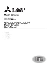
Motion Controller
Brand:
Mitsubishi Electric
| Category:
Controller
| Size: 2.8 MB
Table of Contents
Safety Precautions
2
Revisions
12
Table of Contents
13
About Manuals
17
1 Overview
20
Functional Overview
22
System Configuration
24
Q173DSXY Safety Signal Module
26
Applicable Standard
27
Risk Assessment
28
Safety Signal Comparison
29
Speed Monitoring Function (SLS)
29
Safe Speed Monitor (SSM)
30
Shut-Off Function (STO, SS1)
31
Standstill Monitoring (SOS, SS2)
32
Safety Communication Function
33
Restrictions
34
Equipment Configuration of Safety Observation Function Compatible Motion Controller
36
2 Safety Observation Function
38
Configuration of Safety Observation Function
38
Sequence Programs for Safety Observation on PLC CPU
40
Activity Check in Sequence Programs for Safety Observation
43
Safety Signals Comparison
44
Re-Start after Error
44
Speed Monitoring Function (SLS)
45
System Configuration of Speed Monitoring Function
45
Timing of Speed Monitoring Function
48
Example of Speed Monitoring Start Operation
49
Parameter Consistency Check
50
Comparison of Speed Monitoring Parameter
50
Speed Command Observation
50
Feedback Speed Observation
51
Position Feedback Monitoring
51
Speed Deviation Monitoring
52
External Auxiliary Pulse Input Observation
53
Continuous Standstill During Speed Monitoring
53
Speed Error Detection Check
53
Safe Speed Monitor (SSM)
54
Shut-Off Function (STO/SS1)
55
Sequence Program Example for Shut-Off Function (STO/SS1 (Stop Category 1))
55
Standstill Monitoring (SOS, SS2)
57
Encoder Consistency Check by Small Oscillation During Standstill Monitoring
57
Sequence Program Example for Standstill Monitoring (SOS, SS2 (Stop Category 2))
59
Sequence Program Example for Small Oscillation During Standstill Monitoring
61
Sequence Program Example for Safe Break Control (SBC)
62
Safety Communication
63
Functional Safety Signal
66
Sequence Program Example for Shut-Off Function (STO, SS1 (Stop Category 1))
69
Sequence Program Example for Standstill Monitoring (SOS, SS2 (Stop Category 2))
71
Sequence Program Example for Speed Monitoring (SLS1 to SLS4)
73
Checking the Connection Status of Safety Communication
75
SSCNET Communication Condition Monitor
76
Self-Diagnosis Function
77
Safety Signal Output Check Function
77
Memory Check Function
79
Internal Processing Check of Safety Observation Function
79
Scan Time Check
80
Voltage Monitoring of Motion CPU Circuit
80
Temperature Monitoring of Motion CPU Module
80
Speed Monitoring Function Omitting External Auxiliary Pulse Input
81
3 Start-Up Procedures
84
Start-Up Procedures Flow Chart
84
Communication between GX Works2/Gx Developer and Motion CPU
86
PLC Memory Formating
87
Parameters Setting
88
Parameter Setting of Motion CPU
88
Parameter Settings for PLC CPU
94
Creating User Safety Sequence Program
100
Creating PLC CPU Side User Safety Sequence Program
100
Creating Motion CPU Side User Safety Sequence Program
102
Validation of Parameter or Program
112
How to Validate Parameter
112
How to Validate User Safety Sequence Program
113
4 Dedicated Devices
114
Special Relay/Special Register for Safety Observation Function
114
Device Used in Sequence Programs for Safety Observation on PLC CPU Side
116
Multiple CPU Shared Device for Safety Observation Functions
117
Shared Device List for Safety Signal Comparison
118
Detailed Description of Shared Device for Safety Signal Comparison
119
Shared Device List for Speed Monitoring
126
Detailed Description of Shared Device for Speed Monitoring
127
Shared Device List for Safety Communication
134
Detailed Description of Shared Device for Safety Communication
135
5 Sequence Instructions for Motion Cpu
142
Description of the Device for the Sequence Program
142
Input/Output (X, Y)
142
Internal Relays (M, F)
143
Special Relays (SM)
144
Timer (T)
144
Counter (C)
146
Data Register (D)
146
Link Register (W)
147
Index Registers (Z)
147
Nesting (N)
148
Pointer (P)
149
Special Register (SD)
149
Decimal Constant (K)
150
Hexadecimal Constant (H)
150
Configuration of Instructions
151
How to Read the Instruction Table
151
Number of Steps
152
END Instruction
153
Index Ornament
153
Digit Designation
154
Basic Instructions
157
Operation Start, Series Connection, Parallel Connection: LD, LDI, AND, ANI, OR, ORI
157
Ladder Block Series Connection and Parallel Connection: ANB, ORB
158
Out Instruction: out (Excluding Timers, Counters)
159
Timers: out T
160
Counter: out C
162
Setting and Resetting Devices: SET, RST
163
Setting and Resetting the Master Control: MC, MCR
164
Leading Edge and Trailing Edge Outputs: PLS, PLF
166
Bit Device Shifts: SFT
167
Operation Results Push, Read, Pop: MPS, MRD, MPP
168
Function Instructions
169
16-Bit Data Comparisons
169
32-Bit Data Comparisons: D=, D<, D
170
BIN 16-Bit Addition and Subtraction Operations
171
BIN 32-Bit Addition and Subtraction Operations: D+, D
173
BIN 16-Bit Multiplication and Division Operations
175
BIN 32-Bit Multiplication and Division Operations: D*, D
177
Incrementing and Decrementing 16-Bit bin Data: INC, DEC
179
Incrementing and Decrementing 32-Bit bin Data: DINC, DDEC
180
Conversion from bin to BCD (16 Bits, 32Bits): BCD, DBCD
181
Conversion from BCD to bin (16 Bits, 32Bits): BIN, DBIN
183
16-Bit and 32-Bit Data Transfers: MOV, DMOV
185
16-Bit and 32-Bit Data Exchanges: XCH, DXCH
186
Block 16-Bit Data Transfers: BMOV
187
Identical 16-Bit Data Block Transfers: FMOV
188
Pointer Branch Instructions: CJ
189
End Main Routine Program: FEND
191
Call/Return of Subroutine Program: CALL, RET
192
Logical Products with 16-Bit Data: WAND
193
Logical Product with 32-Bit Data: DAND
194
Logical Sums with 16-Bit Data: WOR
195
Logical Sum with 32-Bit Data: DOR
196
16-Bit Exclusive or Operation: WXOR
197
32-Bit Exclusive or Operation: DXOR
198
Complement of 2 of bin 16-Bit Data: NEG
199
Right Rotation of 16-Bit Data: ROR, RCR
200
Right Rotation of 32-Bit Data: DROR, DRCR
202
Left Rotation of 16-Bit Data: ROL, RCL
204
Left Rotation of 32-Bit Data: DROL, DRCL
206
N-Bit Shift to Right or Left of 16-Bit Data: SFR, SFL
208
1-Word Shift to Right or Left of N-Word Data: DSFR, DSFL
210
16-Bit Data Searches: SER
212
16-Bit Data Checks: SUM
213
Decoding from 8 to 256 Bits: DECO
214
7-Segment Decode: SEG
216
Calculation of Average Value: S.AVE
218
6 Troubleshooting
220
Safety Observation Error List
220
Safety Observation Warning List
227
How to Correct Errors of Motion CPU Side Sequence Program
229
Troubleshooting When the Error "CAN'T EXE. PRG" Occurs in a PLC CPU
232
Appendices
234
APPENDIX 1 Functions of GX Works2/Gx Developer Available for Motion CPU
234
APPENDIX 1.1 GX Works2 Features Support
234
APPENDIX 1.2 GX Developer Features Support
241
APPENDIX 2 Example of Checklist for User Documentation
247
Advertisement
Mitsubishi Electric Melsec-Q172DSCPU User Manual (264 pages)
Motion Controller
Brand:
Mitsubishi Electric
| Category:
Controller
| Size: 3.52 MB
Table of Contents
Safety Precautions
2
Revisions
12
Table of Contents
14
About Manuals
17
Manual Page Organization
19
Discontinued Models
20
1 Overview
22
Differences between Q173D(S)CPU/Q172D(S)CPU and Q173HCPU/Q172HCPU
25
Restrictions by the Software's Version
27
Programming Software Version
33
2 System Configuration
34
Motion System Configuration
34
Q173DSCPU/Q172DSCPU System Overall Configuration
37
Q173DCPU(-S1)/Q172DCPU(-S1) System Overall Configuration
39
Function Explanation of the Motion CPU Modules
40
Restrictions on Motion Systems
41
Checking Serial Number and Operating System Software Version
46
Checking Serial Number
46
Checking Operating System Software Version
49
System Configuration Equipment
51
General Specifications
58
Specifications of Equipment and Settings
59
Name of Parts for CPU Module
59
Power Supply Module
79
Base Unit and Extension Cable
87
Q172DLX Servo External Signals Interface Module
91
Q172DEX Synchronous Encoder Interface Module
96
Q173DPX Manual Pulse Generator Interface Module
105
Q173DSXY Safety Signal Module
113
Manual Pulse Generator/Serial Absolute Synchronous Encoder
123
SSCNET Cables
125
Battery
130
Forced Stop Input Terminal
134
3 Design
136
System Designing Procedure
136
External Circuit Design
139
Power Supply Circuit Design
143
Safety Circuit Design
144
Layout Design Within the Control Panel
146
Mounting Environment
146
Calculating Heat Generation by Motion Controller
147
Design Checklist
150
4 Installation and Wiring
152
Module Installation
152
Instructions for Handling
152
Instructions for Mounting the Base Unit
155
Installation and Removal of Module
158
Instructions for Mounting of the Battery Holder Unit
161
Connection and Disconnection of Cable
162
SSCNET Cable
162
Battery Cable
168
Forced Stop Input Cable
170
Internal I/F Connector Cable
171
Mounting of Battery
172
Mounting of Serial Absolute Synchronous Encoder
174
Wiring
175
Instructions for Wiring
175
Connecting to the Power Supply Module
178
5 Start-Up Procedures
180
Check Items before Start-Up
180
Start-Up Adjustment Procedure
182
Operating System Software Installation Procedure
186
Trial Operation and Adjustment Checklist
188
6 Inspection and Maintenance
190
Maintenance Works
191
Instruction of Inspection Works
191
Daily Inspection
193
Periodic Inspection
194
Life
195
Battery
196
Battery Life
197
Battery Replacement Procedure
199
Resuming Operation after Storing the Motion Controller
203
Symbol for the New EU Battery Directive
203
Troubleshooting
204
Troubleshooting Basics
204
Troubleshooting of Motion CPU Module
205
Confirming Error Code
218
Internal Input Circuit Troubleshooting
219
7 Emc Directives
222
Requirements for Compliance with the EMC Directive
222
Standards Relevant to the EMC Directive
223
Installation Instructions for EMC Directive
224
Parts of Measure against Noise
227
Example of Measure against Noise
229
Appendices
232
APPENDIX 1 Cables
232
APPENDIX 1.1 SSCNET Cables
232
APPENDIX 1.2 Serial Absolute Synchronous Encoder Cable
235
APPENDIX 1.3 Battery Cable
238
APPENDIX 1.4 Forced Stop Input Cable
239
APPENDIX 1.5 Internal I/F Connector Cable
240
APPENDIX 1.6 RIO Cable
245
APPENDIX 1.7 SSCNET Cables (SC-J3BUS M-C) Manufactured by Mitsubishi Electric
246
System & Service Co., Ltd
246
APPENDIX 2 Exterior Dimensions
247
APPENDIX 2.1 Motion CPU Module
247
APPENDIX 2.2 Servo External Signals Interface Module (Q172DLX)
250
APPENDIX 2.3 Synchronous Encoder Interface Module (Q172DEX)
250
APPENDIX 2.4 Manual Pulse Generator Interface Module (Q173DPX)
251
APPENDIX 2.5 Safety Signal Module (Q173DSXY)
251
APPENDIX 2.6 Power Supply Module
252
APPENDIX 2.7 Battery Holder Unit (Q170DBATC)
254
APPENDIX 2.8 Connector
255
APPENDIX 2.9 Manual Pulse Generator (MR-HDP01)
260
APPENDIX 2.10 Serial Absolute Synchronous Encoder
261
Advertisement
Related Products
Mitsubishi Electric Melsec-Q172DCPU
Mitsubishi Electric Melsec-Q172DCPU-S1
Mitsubishi Electric Melsec-Q173DCPU
Mitsubishi Electric Melsec-Q173DCPU-S1
Mitsubishi Electric Melsec-Q173DSCPU
Mitsubishi Electric MELSEC-Q10UD(E)HCPU
Mitsubishi Electric MELSEC-Q13UDVCPU
Mitsubishi Electric MELSEC-Q13UDPVCPU
Mitsubishi Electric MELSEC-Q13UD(E)HCPU
Mitsubishi Electric MELSEC-Q100UDEHCPU
Mitsubishi Electric Categories
Air Conditioner
Controller
Projector
Inverter
Heat Pump
More Mitsubishi Electric Manuals
Login
Sign In
OR
Sign in with Facebook
Sign in with Google
Upload manual
Upload from disk
Upload from URL