Sign In
Upload
Manuals
Brands
Mitsubishi Electric Manuals
Controller
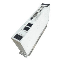
MELDAS MDS-R-V2-6060
Mitsubishi Electric MELDAS MDS-R-V2-6060 Manuals
Manuals and User Guides for Mitsubishi Electric MELDAS MDS-R-V2-6060. We have
1
Mitsubishi Electric MELDAS MDS-R-V2-6060 manual available for free PDF download: Technical Specification And Instruction Manual
Mitsubishi Electric MELDAS MDS-R-V2-6060 Technical Specification And Instruction Manual (285 pages)
Brand:
Mitsubishi Electric
| Category:
Controller
| Size: 4.55 MB
Table of Contents
Table of Contents
17
Introduction
21
System Configuration
22
Explanation of Type
23
Servomotor Type
23
Servo Drive Unit Type
24
Specifications
25
Servomotor
26
Specifications List
26
Torque Characteristics
27
Outline Dimension Drawings
28
Servo Drive Unit
40
Installation Environment Conditions
40
Specifications List
40
Outline Dimension Drawings
41
Explanation of each Part
45
Characteristics
47
Drive Unit Characteristics
48
Heating Value
48
Overload Protection Characteristics
49
Servomotor
53
Shaft Characteristics
53
Magnetic Brake
54
Dynamic Brake Characteristics
57
Dedicated Options
59
Regenerative Option
60
Regenerative Resistor Unit
62
Regenerative Resistor
64
Machine Side Detector
66
Battery and Terminator Option
67
Terminator (A-TM)
67
Battery (ER6)
68
Battery Unit (MDS-A-BT)
69
Relay Terminal Block (MR-J2CN3TM)
70
Cables and Connectors
71
Cable Connection Diagram
71
Cable and Connector Options
72
Peripheral Devices
77
Selecting the Wire Size
78
Example of Wires by Unit
78
Selection of No-Fuse Breaker and Contactor
80
Selection of No-Fuse Breaker
80
Selection of Contactor
81
Selection of Earth Leakage Breaker
82
Selection of Control Power Supply
83
Noise Filter
84
Surge Absorber
85
Relay
86
Installation
87
Installing the Servomotor
88
Environmental Conditions
88
Vibration-Resistance Strength
88
Precautions for Mounting Load (Preventing Impact on Shaft)
89
Installation Direction
89
Oil and Waterproofing Measures
89
Cable Stress
91
Installation of the Units
92
Environmental Conditions
92
Installation Direction and Clearance
93
Prevention of Foreign Matter Entry
96
Panel Installation Hole Machining Drawings (Panel Cut Drawings)
96
Heating Value
97
Heat Radiation Countermeasures
98
Noise Measures
101
Wiring and Connection
103
Part System Connection Diagram
105
Main Circuit and Control Circuit Connectors
106
Connector Pin Assignment
106
Main Circuit and Control Circuit Connector Signal Names and Applications
107
NC and Drive Unit Connection
108
Motor and Detector Connection
109
Connection of Servomotor HF Series
109
Connection of Main Circuit Power Supply
112
Connection of Regenerative Resistor
113
Connection of External Option Regeneration Resistance Unit
113
Connection of External Regenerative Resistor
114
Wiring of Contactors
116
Contactor Control
116
Contactor Control Signal (MC) Output Circuit
117
Contactor Power on Sequences
118
Contactor Shutoff Sequences
118
Monitor of Contactor Operation
119
Wiring of the Motor Brake
120
Motor Brake Control Signal (MBR) Output Circuit
120
Motor Brake Release Sequence
121
Control During the Servo off Command
121
Operation Sequences When an Emergency Stop Occurs
121
Wiring of an External Emergency Stop
122
External Emergency Stop Setting
122
External Emergency Stop Signal (EMGX) Input Circuit
123
External Emergency Stop Operation Sequence
124
Setup
125
Servo Drive Unit Initial Settings
126
Setting the Rotary Switch
126
Transition of LED Display after Power Is Turned on
127
Setting the Initial Parameters
128
Setting the Standard Parameters
128
Limitations to Electronic Gear Setting Value
132
Standard Parameter List According to Servomotor
133
List of Parameters
135
Adjustment
145
Servo Adjustment Data Output Function (D/A Output)
146
D/A Output Specifications
146
Setting the Output Data
146
Setting the Output Magnification
147
Current Feedback Analog Output Function
147
Gain Adjustment
148
Current Loop Gain
148
Speed Loop Gain
148
Position Loop Gain
150
Characteristics Improvement
153
Optimal Adjustment of Cycle Time
153
Vibration Suppression Measures
155
Improving the Cutting Surface Precision
159
Improvement of Protrusion at Quadrant Changeover
162
Improvement of Overshooting
167
Improvement of Characteristics During Acceleration/Deceleration
169
Settings for Emergency Stop
172
Deceleration Control
172
Vertical Axis Drop Prevention Control
174
Vertical Axis Pull up Control
176
Troubleshooting
177
Points of Caution and Confirmation
178
Troubleshooting at Start up
179
List of Unit Protection Functions
180
List of Alarms
180
List of Warnings
182
Troubleshooting According to Alarm and Warning Number
183
Alarms
183
Warning
194
Parameter No. During Initial Parameter Error
196
Characteristics
197
Inspections
198
Service Parts
198
Appendix 1. Cable and Connector Specifications
199
Appendix 1-1 Selection of Cable
200
Appendix 1-1-1 Cable Wire and Assembly
200
Appendix 1-2 Cable Connection Diagram (SVJ2-6-4-5, 6-22P)
202
Appendix 1-3 Connector Outline Dimension Drawings
206
Appendix 1-4 Cable and Connector Assembly
211
Appendix 1-4-1 CM10-SP**S Plug Connector
211
Appendix 1-4-2 CM10-AP**S Angle Plug Connector
218
Appendix 2. Selection
227
Appendix 2-1 Selection of Servomotor Capacity
228
Appendix 2-1-1 Load Inertia Ratio
228
Appendix 2-1-2 Short Time Characteristics
228
Appendix 2-1-3 Continuous Characteristics
229
Appendix 2-2 Selecting the Regenerative Resistor
231
Appendix 2-2-1 Calculating the Regenerative Energy
231
Appendix 2-2-2 Calculating the Positioning Frequency
233
Appendix 2-3 Example of Servo Selection
234
Appendix 2-3-1 Motor Selection Calculation
234
Appendix 2-3-2 Regenerative Resistor Selection Calculation
237
Appendix 2-3-3 Servo Selection Results
239
Appendix 2-4 Motor Shaft Conversion Load Torque
240
Appendix 2-5 Expressions for Load Inertia Calculation
241
Appendix 3. Compliance with European EC Directives
243
Appendix 3-1 Compliance to EC Directives
244
Appendix 3-1-1 European EC Directives
244
Appendix 3-1-2 Cautions for EC Directive Compliance
244
Appendix 4. EMC Installation Guidelines
247
Appendix 4-1 Introduction
248
Appendix 4-2 EMC Instructions
248
Appendix 4-3 EMC Measures
249
Appendix 4-4 Measures for Panel Structure
249
Appendix 4-4-1 Measures for Control Panel Unit
249
Appendix 4-4-2 Measures for Door
250
Appendix 4-4-3 Measures for Operation Board Panel
250
Appendix 4-4-4 Shielding of the Power Supply Input Section
250
Appendix 4-5 Measures for Various Cables
251
Appendix 4-5-1 Measures for Wiring in Panel
251
Appendix 4-5-2 Measures for Shield Treatment
251
Appendix 4-5-3 Servo/Spindle Motor Power Cable
252
Appendix 4-5-4 Servo/Spindle Motor Feedback Cable
253
Appendix 4-6 EMC Countermeasure Parts
254
Appendix 4-6-1 Shield Clamp Fitting
254
Appendix 4-6-2 Ferrite Core
255
Appendix 4-6-3 Power Line Filter
256
Appendix 4-6-4 Surge Protector
261
Appendix 5. Instruction Manual for Compliance with Ul/C-UL Standard
263
Appendix 5-1 Operation Surrounding Air Ambient Temperature
264
Appendix 5-2 Notes for AC Servo System
264
Appendix 5-2-1 General Precaution
264
Appendix 5-2-2 Installation
264
Appendix 5-2-3 Short-Circuit Ratings
264
Appendix 5-2-4 Peripheral Devices
264
Appendix 5-2-5 Field Wiring Reference Table for Input and Output
264
Appendix 5-2-6 Motor over Load Protection
264
Appendix 5-2-7 Flange of Servo Motor
264
Appendix5-3 AC Servo/Spindle System Connection
265
Appendix 6. Transportation Restrictions for Lithium Batteries
267
Appendix 6-1 Restriction for Packing
268
Appendix 6-1-1 Target Products
268
Appendix 6-1-2 Handling by User
269
Appendix 6-1-3 Reference
270
Appendix 6-2 Issuing Domestic Law of the United State for Primary Lithium Battery Transportation
271
Appendix 6-2-1 Outline of Regulation
271
Appendix 6-2-2 Target Products
271
Appendix 6-2-3 Handling by User
271
Appendix 6-2-4 Reference
271
Appendix 6-3 Example of Hazardous Goods Declaration List
272
Appendix 7. Compliance with China Compulsory Product Certification (CCC Certification) System
275
Appendix 7-1 Outline of China Compulsory Product Certification System
276
Appendix 7-2 First Catalogue of Products Subject to Compulsory Product Certification
276
Appendix 7-3 Precautions for Shipping Products
277
Appendix 7-4 Application for Exemption
278
Appendix 7-5 Mitsubishi NC Product Subject To/Not Subject to CCC Certification
279
Advertisement
Advertisement
Related Products
Mitsubishi Electric MELDAS MDS-R-V1-20
Mitsubishi Electric MELDAS MDS-R-V1-40
Mitsubishi Electric MELDAS MDS-R-V1-60
Mitsubishi Electric MELDAS MDS-R-V1-80
Mitsubishi Electric MELDAS MDS-R-V2-2020
Mitsubishi Electric MELDAS MDS-R-V2-4040
Mitsubishi Electric MELDAS MDS-R-V2-6040
Mitsubishi Electric MELDAS MDS-R-V2-8040
Mitsubishi Electric MELDAS MDS-R-V2-8060
Mitsubishi Electric MELDAS MDS-R-V2-8080
Mitsubishi Electric Categories
Air Conditioner
Controller
Projector
Inverter
Heat Pump
More Mitsubishi Electric Manuals
Login
Sign In
OR
Sign in with Facebook
Sign in with Google
Upload manual
Upload from disk
Upload from URL