Sign In
Upload
Manuals
Brands
JVC Manuals
VCR
BR-S525U
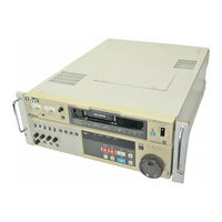
JVC BR-S525U Manuals
Manuals and User Guides for JVC BR-S525U. We have
1
JVC BR-S525U manual available for free PDF download: Service Manual
JVC BR-S525U Service Manual (389 pages)
Brand:
JVC
| Category:
VCR
| Size: 66.34 MB
Table of Contents
Table of Contents
3
Safety Precautions
4
Safety Check after Servicing
5
General Description
6
Detail of Alterations
6
Mechanism Adjustment
7
Changes in Mechanism Assembly
7
A/C Head - Change
8
Pinch Roller Arm Assembly - Change
9
Mode Motor - Change
9
Pinch Roller Solenoid Position - Addition
9
Full Erase Head - Addition
10
Pole Base Assembly - Change
10
Electrical Adjustment
11
Audio Rec Level VR Setting and Audio Level Meter Adjustment
11
Normal Audio Playback Level Adjustment
11
Normal Audio Playback Frequency Response
11
Audio Bias Frequency and Level
12
Normal Audio REC/PB
12
Normal Audio PB Frequency Response - REC/PB
13
Full Erase Frequency
14
BR-S822U Audio Insert Erase Voltage
14
BR-S622U Audio Post-Recording Erase Voltage
14
BR-S822U Normal Audio Insert Crosstalk Cancel
15
BR-S622U Normal Audio Post-Recording Crosstalk Cancel
15
BR-S822 U Normal Audio Insert Bias Trap
15
BR-S622 U Normal Audio Post-Recording Bias Trap
15
BR-S822U Time Code Bias Trap
16
Hi-Fi Audio Carrier Frequency
16
Hi-Fi Audio FM Output Level
16
Hi-Fi Audio PB Level
16
Audio Circuit - BR-S522U/BR-S525U
17
Diagrams and Circuit Boards
19
Expression of Connector
19
Expression of Wiring
19
Signal Flow on the Diagram
19
Circuit Board Locations
20
Overall Wiring Diagram
21
Mother-1 Schematic Diagram
27
Mother-1 Circuit Board Diagram
29
Mother-2 Schematic Diagram
30
Mother-2 Circuit Board Diagram
32
Audio-3 Circuit Board Diagram
33
Audio-3 Schematic Diagram
34
AV Micom/Onscreen Circuit Board Diagram
36
AV Micom/Onscreen Schematic Diagram
37
Mother-1 Circuit Board
38
Exploded Views and Parts List
39
Exploded Part Number Coding
40
Packing Assembly M1
40
Packing Assembly M1 Parts List
41
Cabinet Assembly M2 View
42
Cabinet Assembly M2 Parts List
43
Chassis Assembly M3 View
44
Chassis Assembly M3 Parts List
45
Frame Assembly M4 Parts List
46
Frame Assembly M4 View
47
Rear Bracket Assembly M5 View
48
Rear Bracket Assembly M5 Parts List
49
Mechanism 1 Assembly M6 View
50
Mechanism 1 Assembly M6 Parts List
51
Mechanism 2 Assembly M7 View
52
Mechanism 2 Assembly M7 Parts List
53
Cassette Housing Assembly M8 Parts List
54
Cassette Housing M8 View
55
Drum Assembly M9A/M9B View and Parts List
56
Electrical Parts List
57
Front Panel Assembly
61
Cassette Panel Assembly MA View and Parts List
61
Operation Panel Assembly MB View and Parts List
62
AV M/ONSC Board Assy 41 Parts List
64
Specifications
69
Comparison Table of Different Parts and Function by Model
71
Precautions During Servicing
74
Precautions
78
Features
78
Controls and Connectors
79
Front Sub-Panel Overview
81
Rear Panel
82
Connections - Video Equipment
83
Connections - Audio Equipment
83
Reference Sync Signals for Recording and Playback
84
Loading and Unloading Video Cassettes
84
On-Screen Displays
85
Playback
85
Shutter Search
86
Jog Search
86
Rewind and Fast-Forward
86
Preroll Playback
86
Recording
87
Recording Level Adjustments
87
Record-Pause and Assemble Editing
87
Time Code/User Bits Recording/Playback
88
ID Code
88
Time Code Editing
88
Preset Recording
88
Guide to Editing
89
Regenerated Recording
89
Quick Guide to Editing Techniques
89
Editing Connections
90
Connections for Swap Editing
90
Connections for A/B Roll Editing
90
Manual Editing
91
Preparing Recording Tapes for Editing
91
Preroll Editing
91
Automatic Editing
92
Run Editing
92
On-Screen Edit Data Display
93
Counter Display
94
Setup Menu
95
ROM Version/Hour Meter Display
99
Warning Display
100
Diagnostic Codes
100
Test Points
101
Automatic Equaliser
101
Installation
101
Rack Mounting
101
Connector Specifications
102
Controls and Connectors Overview
104
Front Sub-Panel
106
Audio Dubbing
108
Menu Settings
108
Removal of External Covers
113
Removal of Main Boards
114
Internal Switches
117
RP y Switches
117
R/P Color 2 Switches
117
R/P Adjust Switches
117
Y Comb Switches
118
Output Switches
118
M. CTL & R. Servo Switches
119
TBC-1 Switches
120
TBC-3 Switches
120
Time Code G/R Switches
121
45 Pin Main Switches
121
RS-232C Switches
121
Memory Switch Initialization
122
Indication of ROM and Microprocessor Versions
122
7-Pin Cable
123
When in Trouble
124
To Take Cassette out of Set Manually
124
Video System Problems
124
Audio System Problems
125
Operational System Problems
125
Syscon System Problems
125
Mechanism System Problems
126
Check of Supply Voltage
126
Protocol of 9-Pin Remote Connector
127
Specification of 9-Pin Connector
127
Communication Format
127
Command Format
128
Command Table
128
Command from Controller
131
BR-S822E/622E/522E Status Data
137
Return from Device
139
Detail Timing Chart
141
Wide Aspect ID
142
Adjustment Mode
142
Mechanism Adjustment Description
143
Jigs and Special Tools for Mechanism Adjustment
143
Mechanism Operation Check
143
Precautions Replacement of Main Parts
144
Location of Main Parts
145
Cleaning
146
Oiling and Greasing
146
Replacement of Main Parts
147
Cassette Housing Assembly Replacement
147
Cassette Housing Motor Replacement
148
Brush Assembly Replacement
149
Upper Drum Assembly Replacement
150
Centering of Upper Drum - to Remove Upper Drum Wobbling in the Rim
152
Cautions to Handle Microchecker
152
Drum Assembly Replacement
153
A/C Head Replacement
154
Mechanism Assembly Replacement
155
Tension Arm Replacement
155
Pinch Roller Arm Assembly Replacement
155
Capstan Motor Replacement
156
Reel Motor Replacement
156
Loading Motor Replacement
156
Main Brake, TU Sub Brake Replacement
157
Pole Base Assembly Replacement
157
Assembling of Mechanism
158
Mechanism Parts Arrangement
159
Adjustment of Reel Servo Circuit
160
Tension Sensor Position
160
Arrangement of Test Points and Vrs
161
Hall Element Output Bias
161
Hall Element Output Gain
161
Loading Torque
162
Reel FG Duty
163
Play Mode Back Tension
163
Reverse (X1) Torque
163
Tension Warning Data Setting
164
Interchangeability Adjustment
165
Names of Main Parts
165
FM Waveform Check
165
Linearity Adjustment
166
A/C Head Adjustment
168
X Value Adjustment
169
Adjustment of Tape Transport System
170
Supply Guide Roller Height Adjustment
170
Take-Up Guide Pole Height Adjustment
171
Guide Arm Foller Height Adjustment
171
Tension Pole Perpendicularity (Vertical Centering) Check
172
Electrical Adjustments
173
Required Tools and Test Instruments
173
Specification of Alignment Tapes
174
Signals Required for Video System Adjustment
175
Main Boards Location
176
Initial Setting of Front and Rear Panel Switches at Shipment
176
Explanation of Main Columns in Check and Adjustment
177
Check Point Column
177
Signal Column/Mode Column
177
About RAP Mode
177
D/C Servo Circuit
178
Capstan FG Duty Factor and Level
178
Tracking Preset
178
PB Switching Point
178
Audio Circuit
179
Audio REC Level VR Setting & Audio Level Meter Adjustment
179
Normal Audio Playback Level
179
Normal Audio Playback Frequency Response Check and Adjustment
179
Audio Bias Frequency and Level Check and Adjustment
180
Normal Audio REC/PB Check and Adjustment
180
Normal Audio PB Frequency Response (REC/PB)
181
Full Erase Frequency Check and Adjustment
182
BR-S822 Audio Insert Erase Voltage
182
BR-S622 Audio Post-Recording Voltage
182
BR-S822 Normal Audio Insert Crosstalk Cancel
183
BR-S622 Normal Audio Post-Recording Crosstalk Cancel
183
BR-S822 Normal Audio Insert Bias Trap
184
BR-S822 Time Code Bias Trap
184
Hi-Fi Audio Carrier Frequency Check/Adjustment
184
Hi-Fi Audio FM Output Level Check/Adjustment
184
Hi-Fi Audio PB Level Check/Adjustment
185
Hi-Fi Audio REC FM Level
185
Hi-Fi Audio REC/PB Level
185
Video Circuit
186
Vcxo/Agc
186
Video Input Level
186
Y/C 443 y Input Level
186
E-E Color Input Level
187
Video Level Meter
187
Sub-Emphasis Input Level
187
Carrier and Deviation
188
White and Dark Clip
188
S-VHS Mode Detection - PB Mode
189
Modulation Balance
189
PB Sub-Demphasis
189
RF Equalizer
190
REC FM Level
191
REC Frequency Response
192
Tracking Meter
193
Y Output Level
193
PB VCO/PB Subcarrier
193
E-E Pilot Burst Phase
193
REC Color Level
194
DG Comp
195
E-E Pilot Burst Level
196
Color DOC
196
Crosstalk Cancel
196
Cnr
197
CNR Feedback Ratio
197
PB Pilot Burst Phase Detct
198
CRI Equalizer
198
Afc
198
REF. Burst
199
Color Output Level
199
Auto Equalizer
200
Pilot Burst Delete
201
S-VHS Sideband Comparator
201
REC Y/C Delay
201
PB Y/C Delay
202
2Fc Cancel
202
ADD V Pulse
202
On Screen
203
VITC SEP Clamp Voltage
203
Location of Test Points and Adjustment Parts
204
Sub Panel Circuit
206
Video Phase
206
Genlock SC Phase
206
Diagrams and Printed Circuit Boards
207
Key to Abbreviations
208
Replacing Subminature "Chip" Parts
210
Shapes of Transistors and Diodes
211
Locations of Circuit Boards
212
REC/PB y Block Diagram
213
REC/PB Color-1 Block Diagram
214
REC/PB Color-2 Block Diagram
215
R/P Adjust Block Diagram
216
Output Block Diagram
217
Y Comb Block Diagram
218
Drum/Capstan Servo Block Diagram
219
Hi-Fi Audio Block Diagram
220
Normal Audio Block Diagram
221
AV Micom/Onscreen Block Diagram
222
Syscon Block Diagram
223
M-CTL and Reel Servo Block Diagram
224
Wiring Diagram
225
Mother Board-1 Schematic Diagram
228
Mother Board-1 Circuit Board
229
Mother Board-2 Schematic Diagram
230
Mother Board-2 Circuit Board
232
Slotmother Schematic Diagram
233
Syscon Mother Schematic Diagram
233
Syscon Mother and Slot Mother Circuit Boards
234
Fuse Schematic Diagram
234
Deck Terminal Schematic Diagram
235
Deck Terminal and Cassette Housing Circuit Boards
235
REC/PB y Schematic Diagram
236
DV Voltage - R/P y
238
REC/PB y Circuit Board
240
REC/PB Color Circuit Board
241
DC Voltage - R/P Color
242
REC/PB Color-1 Schematic Diagram
244
Burst Gate
245
Wiring Table
245
Main Waveforms of REC/PB Color Circuit
245
REC/PB Color-2 Schematic Diagram
246
DC Voltage - R/P Color 2
247
REC/PB Color-2 Circuit Board
249
REC/PB Adjust Schematic Diagram
250
REC/PB Adjust Circuit Board
251
DC Voltage - R/P Adjust
252
Y Comb Schematic Diagram
254
DC Voltage - y Comb
255
Y Comb Circuit Board
257
Output Schematic Diagram
258
DC Voltage - Output
260
Output Circuit Board
262
PRE/REC Schematic Diagram and Circuit Board
263
FM Audio PRE/REC Schematic Diagram and Circuit Board
263
Audio-1 Schematic Diagram
264
DC Voltage
267
Audio-1 Circuit Board
269
Audio-2 Schematic Diagram
270
Audio-2 Circuit Board
271
Audio-3 Schematic
272
Audio-3 Circuit Board
276
XLR (Audio-4, -5) Schematic Diagram
277
XLR (Audio-4, -5) Circuit Board
278
Front (Audio-6, Jack, VR) Schematic Diagram
279
Front (Audio-6, Jack, VR) and A/C Head Circuit Board
280
Drum/Capstan Servo Schematic Diagram
281
Drum/Capstan Servo Circuit Board
282
Mechacontrol/Reel Servo Circuit Board
283
Mechacontrol/Reel Servo Schematic Diagram
286
Syscon Schematic Diagram
288
Syscon Circuit Board
289
AV Micom/Onscreen Schematic
290
AV Micom/Onscreen and Counter Display Circuit Boards
291
Operation Schematic Diagram
292
Operation Circuit Board
293
Operation CPU
293
Operation Key-1/2
293
Rear (Rear-1 to -3) Schematic Diagram
294
Rear (Rear-1 to -3) Circuit Board
295
Subpanel Schematic Diagram
296
Subpanel Circuit Board
296
Meter Schematic Diagram
297
Meter Circuit Board
297
Switching Regulator Schematic Diagram
298
IC Block Diagram
299
Exploded Views/ Parts List
309
Packing Assembly M1 Exploded View and Parts List
310
Initial Setting of Front and Rear Panel Switches
311
Cabinet Assembly M2 Exploded View
312
Cabinet Assembly M2 Parts View
313
Chassis Assembly M3 Exploded View
314
Frame Assembly M4 Exploded View
317
Rear Frame Assembly M5 Exploded View
318
Rear Frame Assembly M5 Parts View
319
Mechanism-1 Assembly M6 Exploded View
320
Mechanism-1 Assembly M6 Parts List
321
Mechanism-2 Assembly M7 Exploded View and Parts List
322
Cassette Housing Assembly M8 Parts
324
Cassette Housing Assembly M8 Exploded View
325
Drum Assembly M9 Exploded View and Parts List
326
Cassette Panel Assembly MA Exploded View
326
Operation Panel Assy MB Exploded View
326
Cassette Panel Assembly MA Parts List
327
Operation Panel Assy MB Parts List
327
List of Electrical Parts
329
Advertisement
Advertisement
Related Products
JVC BR-S622U
JVC BR-S522U
JVC BR-S822U
JVC BR-S500E
JVC BR-S800E
JVC BR-S622E
JVC BR-S525E
JVC BR-DV3000E
JVC BR-D95U
JVC BR-DV6000
JVC Categories
Car Receiver
Camcorder
TV
VCR
Stereo System
More JVC Manuals
Login
Sign In
OR
Sign in with Facebook
Sign in with Google
Upload manual
Upload from disk
Upload from URL