Sign In
Upload
Manuals
Brands
HP Manuals
Server
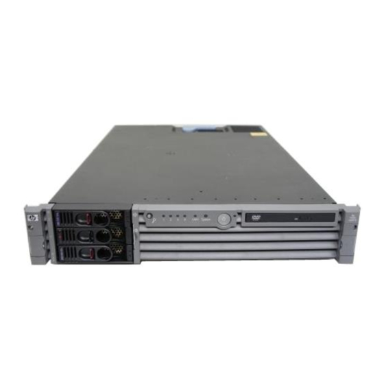
9000 rp3440
HP 9000 rp3440 Manuals
Manuals and User Guides for HP 9000 rp3440. We have
7
HP 9000 rp3440 manuals available for free PDF download: User's & Service Manual, Service Manual, Installation Manual, Manual, Firmware Update Manual, Safety And Regulatory Information Manual
HP 9000 rp3440 Service Manual (210 pages)
User Service Guide, Sixth Edition - HP 9000 rp3410/rp3440
Brand:
HP
| Category:
Server
| Size: 11.31 MB
Table of Contents
Table of Contents
3
About this Document
15
Intended Audience
15
New and Changed Information in this Edition
15
Publishing History
15
Document Organization
15
Publishing History Details
15
Typographic Conventions
16
HP-UX Release Name and Release Identifier
16
Physical and Environmental Specifications
16
Related Documents
17
Contacting HP
17
Before You Contact HP
17
HP-UX 11I Releases
17
HP Contact Information
18
Subscription Service
18
Documentation Feedback
18
Overview
19
HP 9000 Rp3410 and Rp3440 Server Views
19
HP 9000 Rp3410 and Rp3440 Servers - Front View
19
HP 9000 Rp3410 and Rp3440 Servers - Front View with Bezel Removed
19
HP 9000 Rp3410 and Rp3440 Servers - Rear View
19
Detailed Server Description
20
Memory
20
Processor
20
HP 9000 Rp3410 and Rp3440 Servers - Pedestal Mount
20
PCI Riser
21
Internal Core I/O
21
External Core I/O
21
Power Supply Unit
21
System Board Manageability
22
Enhanced Server Manageability Using the Ilo MP
22
Hard Disk Drives
22
Internal RAID
22
Firmware
22
Dimensions and Values
23
Event Ids for Errors and Events
23
System Board
23
Server Dimensions and Values
23
System Board Components
24
PA RISC Processor
24
System Board Block Diagram
24
Processor Bus
25
ZX1 I/O and Memory Controller
25
Memory
25
Memory Architecture
26
Memory Block Diagram
26
Memory Array Capacities
26
Chip Spare Functionality
27
Serial Presence Detect
27
I/O Bus Interface
27
Processor Dependent Hardware Controller
27
Field Programmable Gate Array
28
Bmc
28
SCSI Controller
28
IDE Interface
29
GB System LAN
29
USB Connectors
29
Disk and I/O Path Logging
29
Internal Disk and DVD Paths
29
Extended Core I/O Paths
29
PCI I/O Paths
30
PCI I/O Hardware Paths
30
Controls, Ports, and Leds
31
Control Panel
31
Front View
31
Control Panel Leds and Buttons
32
Control Panel Leds and Switches
32
Additional Controls and Indicators
33
Hot-Pluggable Disk Drive Indicators
33
Optional Removable Media Drive
33
Hot-Pluggable Disk Drive LED Indicators
33
DVD Drive
33
Hot-Pluggable Disk Drive LED Definitions
33
DVD Drive LED Definitions
33
Rear Panel
34
Rear View
34
Rear Panel Connectors and Switches
34
10/100/1000 Base-T Ethernet LAN Connector
35
USB Ports
35
Base-T Ethernet LAN Connector Leds
35
Base-T Ethernet LAN Connector Pinouts
35
SCSI Port, Ultra 3, 68-Pin
36
Dual USB Port Connector
36
Single USB Port
36
USB Pinouts
36
SCSI Port Pinouts
36
Ilo MP Card LAN Leds
37
Powering the Server on and off
38
Power States
38
Ilo MP Card LAN Leds
38
Ilo MP Card LAN Connector Pinouts
38
Powering on the Server
39
Powering off the Server
39
Powering off the Server Using the Ilo MP
39
Powering on the Server Manually
39
Powering on the Server Using the Ilo MP
39
Power States
39
Powering off the Server Manually
40
System Specifications
41
System Configuration
41
Dimensions and Values
41
Server Dimensions and Values
41
Minimum and Maximum System Configurations
41
Grounding
42
Electrical Specifications
42
AC Power Cables
42
Circuit Breaker
42
Server Dimensions and Values
42
Power Cables
42
System Power Specifications
43
Power and Cooling
43
Environmental Specifications
44
Operating Environment
44
Additional Component Power Consumption
44
Environmental Temperature Sensor
45
Nonoperating Environment
45
Cooling
45
Bulk Power Supply Cooling
45
CPU and Memory Cooling
45
PCI and Mass Storage Section Cooling
45
Acoustic Noise Specification
46
Physical and Environmental Specifications
46
Installing the System
47
Introduction
47
Server Views
47
HP 9000 Rp3410/Rp3440 Server - Front View
47
HP 9000 Rp3410/Rp3440 Server - Front View with Bezel Removed
47
HP 9000 Rp3410/Rp3440 Server - Rear View
47
Detailed Server Description
48
Features
48
HP 9000 Rp3410/Rp3440 Server - Pedestal Mount
48
HP 9000 Rp3410 and Rp3440 Server Features
48
Firmware
49
Dimensions and Values
49
Event Ids for Errors and Events
49
Installation Sequence and Checklist
50
Safety Information
50
Installation Sequence Checklist
50
Unpacking and Inspecting the Server
51
Checking the Inventory
51
Inspecting the Shipping Containers for Damage
51
Unpacking the Server
51
Verifying Site Preparation
51
Returning Damaged Equipment
52
Unloading the Server with a Lifter
52
Installing Additional Components
52
Accessing a Rack-Mounted Server
52
Rack-Mounted Server
52
Removing and Replacing Server Covers and Bezels
52
Extend the Server from the Rack
53
Removing and Replacing the Top Cover on a Rack-Mounted Server
53
Release the Rack Latches
53
Removing and Replacing the Top Cover on a Rack-Mounted Server
54
Removing and Replacing the Front Bezel on a Rack-Mounted Server
55
Aligning the Top Cover
55
Closing the Top Cover
55
Front Bezel Retaining Clip
56
Replacing the Front Bezel
56
Accessing a Pedestal-Mounted Server
57
Removing the Side Cover on a Pedestal-Mounted Server
57
Removing the Top Cover on Pedestal-Mounted Server
57
Replacing the Top Cover on a Pedestal-Mounted Server
58
Removing the Top Cover on a Pedestal-Mounted Server
58
Top Cover Alignment Mark
58
Replacing the Side Cover on a Pedestal-Mounted Server
59
Replacing the Top Cover on a Pedestal-Mounted Server
59
Removing and Replacing the Front Bezel on a Pedestal-Mounted Server
60
Removing the Front Bezel on a Pedestal-Mounted Server
60
Installing Internal Hard Disk Drives
61
Aligning the Pedestal Front Bezel
61
Front View of the HP 9000 Rp3410/Rp3440 Server
61
Filler Removal from Slot 1
62
Disk Drive Installation in Slot 3
62
Hard Drive Lock
63
Installing a DVD Drive
64
Installing the DVD Drive
64
DVD Drive Installation
64
Removing and Replacing Airflow Guides
65
Removing and Replacing the Memory Airflow Guide
65
Removing the Memory Airflow Guide
65
Airflow Guides Locations
65
Replacing the Memory Airflow Guide
66
Removing and Replacing the Processor Airflow Guide
66
Removing the Processor Airflow Guide
66
Removing the Memory Airflow Guide
66
Removing the Processor Airflow Guide
67
Removing Fans 1A and 1B
67
Opening the Release Clip
68
Removing the Front Portion of the Processor Airflow Guide
68
Replacing the Processor Airflow Guide
69
Routing the Turbofan Power Cables through Heatsink Posts
69
Installing Additional System Memory
70
Supported DIMM Sizes
70
Installing System Memory
71
Rp3410 Memory Configuration
71
DIMM Slot Identification
71
Memory Loading Rules and Performance Guidelines
72
Rp3440 Memory Configuration
72
System Firmware Requirements
72
Installation Procedure
73
Inserting the DIMM into the Connector
73
Removing and Replacing the PCI Card Cage
74
Removing the PCI Card Cage
74
Installing PCI Cards
75
Replacing the PCI Card Cage
75
Removing the PCI Card Cage Cover
75
Installing a PCI Card
76
Installing an Additional Power Supply
76
Removing the Power Supply Filler Panel
77
Replacing the Power Supply
77
Installing an Additional Processor Module
78
Unlocking the Dual Processor Module Locking Mechanism
79
Aligning the Processor Module
80
Locking the Dual Processor Module in Place
80
Sliding the Sequencing Retainer Plate
81
Securing the Captive Screws
81
Power Module Shims
82
Aligning the Processor Module Power Pod
82
Installing the Processor Module Power Pod Mounting Screws
83
Connecting the Power Pod Cable
84
Routing the Turbofan Power Cables through Heatsink Posts
84
Replacing the System Battery
85
Battery Notice
85
Installing the Server into a Rack, Non-HP Rack, or Pedestal
86
Replacing the System Battery
86
HP Rack
87
Non-HP Rack
87
Pedestal Mount
87
Connecting the Cables
87
AC Input Power
87
Core I/O Connections
87
Applying Standby Power to the Server
88
Connecting to the LAN
88
Console Setup
89
Setup Checklist
89
LAN Ports on the Server Rear
89
Setup Flowchart
90
Preparation
91
Determining the Physical Ilo MP Access Method
91
Ilo MP Setup Flowchart
91
Determining the Ilo MP LAN Configuration Method
92
Configuring the Ilo MP LAN Using DHCP and DNS
92
Console Connection Matrix
92
MP LAN Configuration Methods
92
Configuring the Ilo MP LAN Using ARP Ping
93
ARP Ping Commands
93
Configuring the Ilo MP LAN Using the RS-232 Serial Port
94
Logging in to the Ilo MP
95
Additional Setup
96
Modifying User Accounts and Default Password
96
Security Access Settings
97
Setting up Security
97
Accessing the Host Console
97
Accessing the Host Console with the TUI - CO Command
97
Interacting with the Ilo MP Using the Web GUI
98
Web GUI Login Page
98
Accessing the Graphic Console Using VGA
99
Enabling VGA Graphics Capability
99
Status Summary Page
99
Installing Your A6150B Graphics Card
100
Connecting a Monitor Using the VGA Port
100
Powering the Server on and off
100
Power States
100
Powering off the Server
101
Powering on the Server
101
Powering on the Server Manually
101
Powering on the Server Using the Ilo MP PC Command
101
Power States
101
Powering off the Server Using the Ilo MP PC Command
102
Powering off the Server Manually
102
Booting the Operating System
102
Booting and Shutting down HP-UX
102
Standard HP-UX Booting Using the Boot Console Handler
102
Supported Operating System
102
Booting HP-UX in LVM Maintenance Mode
103
Booting HP-UX in Single-User Mode
103
Shutting down HP-UX
103
Verifying the Server Configuration Using Boot Console Handler
104
Troubleshooting
104
Troubleshooting Methodology
104
Troubleshooting Using the Server Power Button
104
Server Power Button Functions When Server Is on and at BCH
104
Server Does Not Power on
105
Operating System Does Not Boot
105
Server Power Button Functions When Server Is on and os Is Running
105
Server Power Button Functions When Server Is off
105
Operating System Boots with Problems
106
Intermittent Server Problems
106
DVD Problems
106
Hard Drive Problems
106
Console Problems
106
Downloading and Installing the Latest Version of the Firmware
106
Downloading the Latest Version of the Firmware
107
Front Control Panel Leds
107
Installing the Latest Version of the Firmware
107
Troubleshooting Using LED Indicators
107
Control Panel Leds and Buttons
107
Front Control Panel LED Definitions
107
Information to Collect before You Contact Support
108
Booting the Operating System
109
Supported Operating System
109
Booting and Shutting down HP-UX
109
Standard HP-UX Booting Using the Boot Console Handler
109
Booting HP-UX in Single-User Mode
110
Booting HP-UX in LVM Maintenance Mode
110
Shutting down HP-UX
110
Verifying the Server Configuration Using Boot Console Handler
111
Troubleshooting
113
Troubleshooting Methodology
113
Troubleshooting System Power
113
Using the Front Panel Power Button
113
Power Button Functions
113
Operating System Does Boot
114
Operating System Does Not Boot
114
Troubleshooting Using Online Support Tools
114
Event Monitoring Service
114
Support Tools Manager
114
Accessing the Ilo MP Interface and System Logs
115
Ilo MP
115
Sel
115
Troubleshooting Using Offline Support Tools
116
Offline Diagnostic Environment
116
Identifying and Diagnosing Hardware Problems
117
Troubleshooting Using Leds
117
ODE Commands
117
System Board Leds
117
Power and System Leds
118
LAN Leds
118
Control Panel Leds
118
System LED States
118
System Board Leds
119
Base-T Ethernet LAN Connector Leds
119
Ilo MP Card LAN Leds
119
Cleaning Procedures
120
Location of the STBY and BMC Leds
120
Cleaning
121
Advertisement
HP 9000 rp3440 User's & Service Manual (254 pages)
Brand:
HP
| Category:
Server
| Size: 8.8 MB
Table of Contents
Legal Notices
2
Table of Contents
3
About this Document
15
Intended Audience
15
New and Changed Information in this Edition
15
Document Organization
15
Table 1 Publishing History Details
15
Related Documents
17
Table 2. HP-UX 11I Releases
17
Hp Encourages Your Comments
18
Typographic Conventions
16
Overview
19
HP 9000 Rp3410 and Rp3440 Server Views
20
Figure 1-1 HP 9000 Rp3410 and Rp3440 Servers - Front View
20
Figure 1-2 HP 9000 Rp3410 and Rp3440 Servers - Front View with Bezel Removed
20
Figure 1-3 HP 9000 Rp3410 and Rp3440 Servers - Rear View
21
Figure 1-4 HP 9000 Rp3410 and Rp3440 Servers - Pedestal Mount
21
Detailed Server Description
22
Processor
22
Memory
22
PCI Riser
23
Internal Core I/O
23
External Core I/O
23
Power Supply Unit
23
System Board Manageability
23
Enhanced Server Manageability Using the Integrity Ilo MP
24
Hard Disk Drives
24
Internal RAID
24
Firmware
24
Dimensions and Values
25
System Board
25
Table 1-1. Server Dimensions and Values
25
Figure 1-5 System Block Diagram
26
Figure 1-6 Memory Block Diagram
28
Table 1-2. Memory Array Capacities
29
Table 1-3. Internal Disk and DVD Paths
32
Table 1-4. Extended Core I/O Paths
32
Table 1-5 PCI I/O Paths
33
Table 1-6. PCI I/O Hardware Paths
34
Controls, Ports, and Leds
35
Control Panel
35
Figure 1-7 Front View
35
Figure 1-8. Control Panel Leds and Buttons
35
Additional Controls and Indicators
37
Table 1-7. Control Panel Leds and Switches
37
Table 1-8 Hot-Pluggable Disk Drive LED Definitions
37
Figure 1-9 Hot-Pluggable Disk Drive LED Indicators
37
Rear Panel
38
Table 1-9. DVD Drive LED Definitions
38
Figure 1-10 DVD Drive
38
Figure 1-11 Rear View
38
Table 1-10. Rear Panel Connectors and Switches
39
Figure 1-12. 10/100/1000 Base-T Ethernet LAN Connector Leds
39
Table 1-11 10/100/1000 Base-T Ethernet LAN Connector Leds
40
Table 1-12 10/100/1000 Base-T Ethernet LAN Connector Pinouts
40
Figure 1-13 Dual USB Port Connector
40
Table 1-13 USB Pinouts
41
Figure 1-14. Single USB Port
41
Figure 1-15. SCSI Port, Ultra 3, 68-Pin
41
Table 1-14. SCSI Port Pinouts
42
Table 1-15. Ilo MP Card LAN Leds
43
Figure 1-16. Ilo MP Card LAN Leds
43
Powering the Server on and off
44
Power States
44
Table 1-16 Ilo MP Card LAN Connector Pinouts
44
Table 1-17 Power States
44
Powering on the Server
45
Powering off the Server
45
System Specifications
47
System Configuration
47
Table 2-1. Minimum and Maximum System Configurations
47
Dimensions and Values
48
Table 2-2. Server Dimensions and Values
48
Grounding
49
Electrical Specifications
49
AC Power Cords
49
Table 2-3 Power Cords
49
Circuit Breaker
50
System Power Specifications
50
Table 2-4. System Power Specifications
50
Power and Cooling
51
Environmental Specifications
51
Table 2-5 Additional Component Power Consumption
51
Table 2-6 Environmental Specifications
51
Cooling
52
Environmental Temperature Sensor
52
Nonoperating Environment
52
Operating Environment
52
Acoustic Noise Specification
53
Physical and Environmental Specifications
54
Table 2-7. Physical and Environmental Specifications
54
Table
54
Installing the System
55
Introduction
55
Server Views
56
Figure 3-1 HP 9000 Rp3410/Rp3440 Server (Front View)
56
Figure 3-2 HP 9000 Rp3410/Rp3440 Server (Front View with Bezel Removed)
56
Figure 3-3 HP 9000 Rp3410/Rp3440 Server (Rear View)
56
Figure 3-4 HP 9000 Rp3410/Rp3440 Server (Pedestal Mount)
57
Detailed Server Description
58
Table 3-1 HP 9000 Rp3410 and Rp3440 Server Features
58
Safety Information
59
Table 3-2. Server Dimensions and Values
59
Installation Sequence and Checklist
60
Table 3-3 Installation Sequence Checklist
60
Unpacking and Inspecting the Server
61
Verifying Site Preparation
61
Inspecting the Shipping Containers for Damage
61
Unpacking the Server
61
Checking the Inventory
61
Returning Damaged Equipment
62
Unloading the Server with a Lifter
62
Installing Additional Components
63
Removing and Replacing Server Covers and Bezels
63
Figure 3-5 Release the Rack Latches
64
Figure 3-6 Removing and Replacing the Top Cover on a Rack-Mounted Server
65
Figure 3-7 Aligning the Top Cover
65
Figure 3-8 Closing the Top Cover
66
Figure 3-9 Front Bezel Retaining Clip
66
Figure 3-10 Replacing the Front Bezel
67
Figure 3-11 Removing the Side Cover on a Pedestal-Mounted Server
68
Figure 3-12 Removing the Top Cover on a Pedestal-Mounted Server
69
Figure 3-13 Top Cover Alignment Mark
70
Figure 3-14. Replacing the Top Cover on a Pedestal-Mounted Server
70
Figure 3-15 Replacing the Side Cover on a Pedestal-Mounted Server
71
Figure 3-16 Removing the Front Bezel on a Pedestal-Mounted Server
72
Installing Internal Hard Disk Drives
73
Figure 3-17 Aligning the Pedestal Front Bezel
73
Figure 3-18. Front View of the HP 9000 Rp3410/Rp3440 Server
74
Figure 3-19. Filler Removal from Slot 1
75
Figure 3-20. Disk Drive Installation in Slot 3
75
Figure 3-21 Hard Drive Lock
76
Installing a DVD Drive
77
Figure 3-22. DVD Drive Installation
77
Removing and Replacing Airflow Guides
78
Figure 3-23 Airflow Guides Locations
79
Figure 3-24 Removing the Memory Airflow Guide
79
Figure 3-25 Removing the Processor Airflow Guide
80
Figure 3-26 Removing Fans 1A and 1B
81
Figure 3-27 Open the Release Clip
82
Figure 3-28 Remove the Front Portion of the Processor Airflow Guide
82
Figure 3-29 Routing the Turbofan Power Cables through Heatsink Posts
83
Installing Additional System Memory
84
Figure 3-30 DIMM Slot Identification
85
Removing and Replacing the PCI Card Cage
88
Figure 3-31 Inserting DIMM into Connector
88
Figure 3-32 Removing the PCI Card Cage
89
Installing PCI Cards
90
Figure 3-33 Removing the PCI Card Cage Cover
90
Figure 3-34 Installing a PCI Card
91
Installing an Additional Power Supply
92
Figure 3-35 Removing the Power Supply Filler Panel
92
Installing an Additional Processor Module
93
Figure 3-36 Replacing the Power Supply
93
Figure 3-37 Unlocking the Dual Processor Module Locking Mechanism
94
Figure 3-38 Aligning the Processor Module
95
Figure 3-39 Locking the Dual Processor Module in Place
96
Figure 3-40 Slide the Sequencing Retainer Plate
96
Figure 3-41 Secure the Captive Screws
97
Figure 3-42 Power Module Shims
97
Figure 3-43 Aligning the Processor Module Power Pod
98
Figure 3-44 Installing the Processor Module Power Pod Mounting Screws
99
Figure 3-45 Connecting the Power Pod Cable
100
Figure 3-46 Routing the Turbofan Power Cables through Heatsink Posts
101
Replacing the System Battery
102
Figure 3-47 Replacing the System Battery
103
Installing the Server into a Rack, Non-HP Rack, or Pedestal
104
HP Rack
104
Non-HP Rack
104
Pedestal Mount
104
Connecting the Cables
105
AC Input Power
105
Core I/O Connections
105
Applying Standby Power to the Server
106
Connecting to the LAN
106
Figure 3-48. LAN Ports on Server Rear
106
Console Setup
107
Setup Checklist
107
Table 3-4 Setup Checklist
107
Setup Flowchart
108
Figure 3-49 Ilo MP Setup Flowchart
108
Preparation
109
Table 3-5. Console Connection Matrix
109
Table 3-6. LAN Configuration Methods
109
Configuring the Ilo MP LAN Using DHCP and DNS
110
Configuring the Ilo MP LAN Using ARP Ping
110
Table 3-7 ARP Ping Commands
111
Configuring the Ilo MP LAN Using the RS-232 Serial Port
112
Logging in to the Ilo MP
114
Additional Setup
114
Accessing the Host Console
116
Accessing the Host Console with the TUI - CO Command
116
Interacting with the Ilo MP Using the Web GUI
116
Figure 3-50 Web Login Page
116
Accessing the Graphic Console Using VGA
117
Figure 3-51 Status Summary Page
117
Powering the Server on and off
118
Power States
118
Table 3-8 Power States
118
Powering on the Server
119
Powering off the Server
119
Booting the Operating System
120
Supported Operating System
120
Booting and Shutting down HP-UX
120
Verifying the Server Configuration Using Boot Console Handler
122
Troubleshooting
123
Troubleshooting Methodology
123
Troubleshooting Using the Server Power Button
123
Table 3-9. Server Power Button Functions When Server Is on and at BCH
123
Server Does Not Power on
124
Operating System Does Not Boot
124
Table 3-10 Server Power Button Functions When Server Is on and os Is Running
124
Table 3-11 Server Power Button Functions When Server Is off
124
Operating System Boots with Problems
125
Intermittent Server Problems
125
DVD Problems
125
Hard Drive Problems
125
Console Problems
125
Downloading and Installing the Latest Version of the Firmware
126
Troubleshooting Using LED Indicators
126
Table 3-12. Front Control Panel LED Definitions
127
Figure 3-52. Control Panel Leds and Buttons
127
Information to Collect before You Contact Support
129
Booting the Operating System
131
Supported Operating System
131
Booting and Shutting down HP-UX
132
Standard HP-UX Booting Using Boot Console Handler
132
Booting HP-UX in Single-User Mode
133
Booting HP-UX in LVM Maintenance Mode
133
Shutting down HP-UX
133
Verifying the Server Configuration Using Boot Console Handler
134
Troubleshooting
135
Troubleshooting Methodology
135
Troubleshooting System Power
136
Using the Front Panel Power Button
136
Operating System Does Boot
136
Table 5-1. Power Button Functions
136
Operating System Does Not Boot
137
Troubleshooting Using Online Support Tools
137
Support Tools Manager
137
Event Monitoring Service
137
Ilo MP
138
Troubleshooting Using Offline Support Tools
140
Offline Diagnostic Environment (ODE)
140
Table 5-2. ODE Commands
140
Identifying and Diagnosing Hardware Problems
141
Troubleshooting Using Leds
141
Power and System Leds
141
Table 5-3. System LED States
141
Figure 5-1. Control Panel Leds
141
LAN Leds
142
Table 5-4. 10/100/1000 Base-T Ethernet LAN Connector Leds
142
Table 5-5. Ilo MP Card LAN Leds
143
System Board Leds
144
Figure 5-2. Location of the STBY and BMC Leds
144
Cleaning Procedures
145
Table 5-6. System Board Leds
145
Table 5-7 Cleaning
145
HP 9000 rp3440 Installation Manual (96 pages)
Installation Guide, Seventh Edition - HP 9000 rp3410 and HP 9000 rp3440
Brand:
HP
| Category:
Server
| Size: 4.12 MB
Table of Contents
Installation Guide
1
Legal Notices
2
Table of Contents
3
About this Document
9
Table 1 Publishing History Details
9
Document Organization
10
Typographic Conventions
10
Table 2. HP-UX 11I Releases
11
Hp Encourages Your Comments
12
Installing the System
13
Introduction
13
Server Views
14
Figure 1-1 HP 9000 Rp3410/Rp3440 Server (Front View)
14
Figure 1-2 HP 9000 Rp3410/Rp3440 Server (Front View with Bezel Removed)
14
Figure 1-3 HP 9000 Rp3410/Rp3440 Server (Rear View)
14
Figure 1-4 HP 9000 Rp3410/Rp3440 Server (Pedestal Mount)
15
Detailed Server Description
16
Table 1-1 HP 9000 Rp3410 and Rp3440 Server Features
16
Safety Information
17
Table 1-2. Server Dimensions and Values
17
Control Panel
18
Figure 1-5 Front View
18
Additional Controls and Indicators
19
Table 1-3. Hard Disk Drive LED Definitions
19
Figure 1-6 Control Panel
19
Figure 1-7. Hard Disk Drive LED Indicators
19
Rear Panel
20
Table 1-4. DVD Drive LED Definitions
20
Figure 1-8. DVD-ROM or CD-RW/DVD-ROM LED Indicators
20
Table 1-5. Rear Panel Connectors and Switches
21
Figure 1-9 Rear View
21
Installation Sequence and Checklist
22
Unpacking and Inspecting the Server
22
Verifying Site Preparation
22
Table 1-6 Installation Sequence Checklist
22
Inspecting the Shipping Containers for Damage
23
Unpacking the Server
23
Checking the Inventory
23
Returning Damaged Equipment
23
Unloading the Server with a Lifter
23
Installing Additional Components
25
Removing and Replacing Server Covers and Bezels
25
Figure 1-10 Release the Rack Latches
26
Figure 1-11 Removing and Replacing the Top Cover on a Rack-Mounted Server
27
Figure 1-12 Aligning the Top Cover
27
Figure 1-13 Closing the Top Cover
28
Figure 1-14 Front Bezel Retaining Clip
28
Figure 1-15 Replacing the Front Bezel
29
Figure 1-16 Removing the Side Cover on a Pedestal-Mounted Server
30
Figure 1-17 Removing the Top Cover on a Pedestal-Mounted Server
31
Figure 1-18 Top Cover Alignment Mark
32
Figure 1-19. Replacing the Top Cover on a Pedestal-Mounted Server
32
Figure 1-20 Replacing the Side Cover on a Pedestal-Mounted Server
33
Figure 1-21 Removing the Front Bezel on a Pedestal-Mounted Server
34
Installing Internal Hard Disk Drives
35
Figure 1-22 Aligning the Pedestal Front Bezel
35
Figure 1-23. Front View of the HP 9000 Rp3410/Rp3440 Server
36
Figure 1-24. Filler Removal from Slot 1
37
Figure 1-25. Disk Drive Installation in Slot 3
37
Figure 1-26 Hard Drive Lock
38
Installing a DVD Drive
39
Figure 1-27. DVD Drive Installation
39
Removing and Replacing Airflow Guides
40
Figure 1-28 Airflow Guides Locations
41
Figure 1-29 Removing the Memory Airflow Guide
41
Figure 1-30 Removing the Processor Airflow Guide
42
Figure 1-31 Removing Fans 1A and 1B
43
Figure 1-32 Open the Release Clip
44
Figure 1-33 Remove the Front Portion of the Processor Airflow Guide
44
Figure 1-34 Routing the Turbofan Power Cables through Heatsink Posts
45
Installing Additional System Memory
46
Figure 1-35 DIMM Slot Identification
47
Removing and Replacing the PCI Card Cage
50
Figure 1-36 Inserting DIMM into Connector
50
Figure 1-37 Removing the PCI Card Cage
51
Installing PCI Cards
52
Figure 1-38 Removing the PCI Card Cage Cover
52
Figure 1-39 Installing a PCI Card
53
Installing an Additional Power Supply
54
Figure 1-40 Removing the Power Supply Filler Panel
54
Installing an Additional Processor Module
55
Figure 1-41 Replacing the Power Supply
55
Figure 1-42 Unlocking the Dual Processor Module Locking Mechanism
56
Figure 1-43 Aligning the Processor Module
57
Figure 1-44 Locking the Dual Processor Module in Place
58
Figure 1-45 Slide the Sequencing Retainer Plate
58
Figure 1-46 Secure the Captive Screws
59
Figure 1-47 Power Module Shims
59
Figure 1-48 Aligning the Processor Module Power Pod
60
Figure 1-49 Install the Processor Module Power Pod Mounting Screws
61
Figure 1-50 Connecting the Power Pod Cable
62
Figure 1-51 Routing the Turbofan Power Cables through Heatsink Posts
63
Replacing the System Battery
64
Figure 1-52 Replacing the System Battery
65
Installing the Server into a Rack, Non-HP Rack, or Pedestal
66
HP Rack
66
Non-HP Rack
66
Pedestal Mount
66
Connecting the Cables
67
AC Input Power
67
Core I/O Connections
67
Applying Standby Power to the Server
68
Connecting to the LAN
68
Figure 1-53. LAN Ports on Server Rear
68
Console Setup
69
Setup Checklist
69
Table 1-7 Setup Checklist
69
Setup Flowchart
70
Figure 1-54 Ilo MP Setup Flowchart
70
Preparation
71
Table 1-8. Console Connection Matrix
71
Table 1-9. LAN Configuration Methods
71
Configuring the Ilo MP LAN Using DHCP and DNS
72
Configuring the Ilo MP LAN Using ARP Ping
72
Table 1-10 ARP Ping Commands
73
Configuring the Ilo MP LAN Using the RS-232 Serial Port
74
Logging in to the Ilo MP
76
Additional Setup
76
Accessing the Host Console
78
Accessing the Host Console with the TUI - CO Command
78
Interacting with the Ilo MP Using the Web GUI
78
Figure 1-55 Web Login Page
78
Accessing the Graphic Console Using VGA
79
Figure 1-56 Status Summary Page
79
Powering on and Powering off
80
Power States
80
Table 1-11 Power States
80
Powering on the Server
81
Powering off the Server
81
Booting the Operating System
82
Supported Operating System
82
Booting and Shutting down HP-UX
82
Verifying the Server Configuration Using Boot Console Handler
84
Troubleshooting
85
Troubleshooting Methodology
85
Troubleshooting Using the Server Power Button
85
Table 1-12. Server Power Button Functions When Server Is on and at BCH
85
Server Does Not Power on
86
Operating System Does Not Boot
86
Table 1-13 Server Power Button Functions When Server Is on and os Is Running
86
Table 1-14 Server Power Button Functions When Server Is off
86
Operating System Boots with Problems
87
Intermittent Server Problems
87
DVD Problems
87
Hard Drive Problems
87
Console Problems
87
Downloading and Installing the Latest Version of the Firmware
88
Troubleshooting Using Leds
89
Table 1-15. Control Panel Leds and Switches
89
Figure 1-57. Control Panel Leds
89
Table 1-16. System LED States
91
Table 1-17. 10/100/1000 Base-T Ethernet LAN Connector Leds
92
Table 1-18. Ilo MP Card LAN Leds
92
Information to Collect before You Contact Support
93
Advertisement
HP 9000 rp3440 Installation Manual (92 pages)
Brand:
HP
| Category:
Server
| Size: 3.19 MB
Table of Contents
Installation Guide
1
Legal Notices
2
Table of Contents
3
Intended Audience
7
Notational Conventions
7
Related Information
8
1 Server Overview and Unpacking
11
Server Overview
11
Figure 1-1 HP 9000 Rp3410 and HP 9000 Rp3440 Server (Front View)
11
Figure 1-2 HP 9000 Rp3410 and HP 9000 Rp3440 Server (Front View with Bezel Removed)
11
Figure 1-3 HP 9000 Rp3410 and HP 9000 Rp3440 Server (Rear View)
12
Figure 1-4 HP 9000 Rp3410 and HP 9000 Rp3440 Server (Tower Version)
12
Unpacking the Server
13
Unpacking a Non-Racked Server
13
Installing the HP Server into a Rack
14
Converting Server to Rack from Tower and to Tower from Rack
14
2 Installing and Configuring
15
Safety Information
15
Service Tools Required
16
Control Panel
17
Figure 2-1 Front View
17
Figure 2-2 Control Panel
17
Additional Controls and Indicators
20
Hard Disk Drive Indicators
20
Figure 2-3. Hard Disk Drive LED Indicators
20
Optional Removable Media Drive
21
Figure 2-4. DVD-ROM or CD-RW/DVD-ROM LED Indicators
21
Rear Panel
22
Figure 2-5 Rear View
22
10/100/1000 Base-T Ethernet LAN Connector
23
Figure 2-6. 10/100/1000 Base-T Ethernet LAN Connector Leds
23
Figure 2-7. Ilo Manageability Card LAN Leds
24
Ilo Manageability Card LAN Leds
24
Removing and Replacing System Covers and Bezels
25
Rack-Mount System
25
Figure 2-8 Release the Rack Latches
26
Figure 2-9 Removing and Replacing the Metal Cover
27
Figure 2-10 Aligning the Metal Cover
28
Figure 2-11 Closing the Metal Cover
28
Figure 2-12 Front Bezel Retaining Clip
29
Tower Configuration
30
Figure 2-13 Replacing the Front Bezel
30
Figure 2-14 Removing the Plastic Cover
31
Figure 2-15 Removing the Metal Cover
31
Figure 2-16 Metal Cover Alignment Mark
32
Figure 2-17 Replacing the Metal Cover
33
Figure 2-18 Replacing the Plastic Cover
33
Figure 2-19 Front Bezel
34
Figure 2-20 Aligning the Tower Front Bezel
35
Installing Internal Hard Disk Drives
36
Figure 2-21 Front View of the HP 9000 Rp3410/Hp 9000 Rp3440 Server
36
Figure 2-22. Filler Removal from Slot 1
37
Figure 2-23. Disk Drive Installation in Slot 3
37
Figure 2-24 Hard Drive Lock
38
Installing a DVD-ROM Drive
39
Figure 2-25. DVD-ROM Drive Installation
39
Installing the DVD-ROM Drive
40
Removing and Replacing Airflow Guides
41
Removing and Replacing the Memory Airflow Guide
41
Figure 2-26 Airflow Guides Locations
41
Removing and Replacing the Processor Airflow Guide
42
Figure 2-27 Removing the Memory Airflow Guide
42
Figure 2-28 Removing the Processor Airflow Guide
43
Figure 2-29 Removing Fans 1A and 1B
44
Figure 2-30 Open the Release Clip
45
Figure 2-31 Remove the Front Portion of the Processor Airflow Guide
46
Figure 2-32 Routing the Turbofan Power Cables through Heatsink Posts
47
Installing Additional System Memory
48
Supported DIMM Sizes
49
Figure 2-33. DIMM Slot Identification
49
Installing System Memory
50
Figure 2-34 Inserting DIMM into Connector
52
Removing and Replacing the PCI Card Cage
53
Removing the PCI Card Cage
53
Figure 2-35 Removing the PCI Card Cage
53
Replacing the PCI Card Cage
54
Figure 2-36 Removing the PCI Card Cage Cover
54
Installing PCI Cards
55
Installing a PCI Card
55
Figure 2-37 Installing a PCI Card
56
Installing an Additional Power Supply
57
Figure 2-38 Removing the Power Supply Filler Panel
57
Figure 2-39 Replacing the Power Supply
58
Installing an Additional Processor Module
59
Figure 2-40 Unlocking the Dual Processor Module Locking Mechanism
60
Figure 2-41 Aligning the Processor Module
61
Figure 2-42 Locking the Dual Processor Module in Place
62
Figure 2-43 Slide the Sequencing Retainer Plate
62
Figure 2-44 Secure the Captive Screws
63
Figure 2-45 Power Module Shims
63
Figure 2-46 Aligning the Processor Module Power Pod
64
Figure 2-47 Install the Processor Module Power Pod Mounting Screws
65
Figure 2-48 Connecting the Power Pod Cable
66
Figure 2-49 Routing the Turbofan Power Cables through Heatsink Posts
67
Replacing the System Battery
68
Battery Notice
68
Figure 2-50 Replacing the System Battery
68
Replacing the System Battery
69
Configuring the HP 9000 Rp3410 or HP 9000 Rp3440 Server
70
HP 9000 rp3440 Manual (47 pages)
Site Preparation Guide
Brand:
HP
| Category:
Server
| Size: 0.56 MB
Table of Contents
Site Preparation Guide
1
Legal Notices
2
Table of Contents
3
Intended Audience
7
Notational Conventions
7
Related Information
8
Printing History
9
1 System Specifications
11
System Configuration
11
Dimensions and Weights
13
Component Dimensions
13
Grounding
14
Electrical Specifications
15
AC Power Cords
15
Circuit Breaker
15
AC Power Specifications
15
Power Consumption and Cooling
16
Environmental Specifications
18
2 General Site Preparation Guidelines
19
Electrical Factors
19
Computer Room Safety
19
Power Consumption
20
Electrical Load Requirements (Circuit Breaker Sizing)
20
Power Quality
20
Distribution Hardware
21
Grounding Systems
22
System Installation Guidelines
25
Environmental Elements
26
Computer Room Preparation
26
Cooling Requirements
26
Humidity Level (RH)
28
Dust and Pollution Control
28
Metallic Particulate Contamination
29
Electrostatic Discharge (ESD) Prevention
30
Acoustics
30
Facility Characteristics
31
Floor Loading
31
Windows
33
Space Requirements
34
Delivery Space Requirements
34
Operational Space Requirements
34
Floor Plan Grid
34
Conversion Factors and Formulas
36
Conversion Factors
36
Formulas
36
Sample of an Installation Schedule
37
Sample Site Inspection Checklist
38
Delivery Survey
41
Information to Collect before You Contact Support
44
Glossary
45
HP 9000 rp3440 Firmware Update Manual (15 pages)
HP Integrity Servers and HP 9000 Servers Firmware Update Options
Brand:
HP
| Category:
Server
| Size: 0.31 MB
Table of Contents
Table of Contents
3
Introduction
4
HP Firmware Manager
4
HP Integrity and HP 9000 Firmware Update Solutions
5
HP Integrity Systems
5
HP Smart Update Manager (HP SUM)
7
Hp Fm
7
Hp Osifm
7
Hp Ofm
8
Additional Firmware Installation Options
8
EFI Image
8
Ilo 3
8
MP-Initiated
8
Firmware Update Options Comparison
8
Firmware Update Options Comparison
9
Frequently Asked Questions
10
How Can I be Notified When New Firmware Packages Are Available
10
Where Can I Download Firmware Packages
10
How Can I View the Firmware Version Installed on My System
11
When Is a Power down and Reboot Required after Updating Firmware
11
Feedback
12
Glossary
13
A Updating Firmware Using Ilo 3
14
Files to Use to Update through Ilo3
14
How to Update Firmware through Ilo 3
14
HP 9000 rp3440 Safety And Regulatory Information Manual (11 pages)
Safety and Regulatory Information, Fourth Edition - HP 9000 rp3410 and HP 9000 rp3440
Brand:
HP
| Category:
Server
| Size: 0.53 MB
Table of Contents
Safety and Regulatory Information
1
Legal Notices
2
Notational Conventions
4
Product Information
4
Regulatory Information
4
Regulatory Model Number
4
Electrical Safety
5
Electrostatic Discharge (Esd) Precautions
5
Laser Safety
6
Cabinet Safety Precautions
6
Disposal of Waste Equipment by Users in Private Household in the European Union
7
Perchlorate Material - Special Handling May Apply
7
European Union RFI Statement
7
Australia C-Tick Label
9
Taiwan BSMI
9
Taiwan Battery Warning
9
Declaration of Conformity
10
Advertisement
Related Products
HP 9000 rp7420
HP 9000 rp3410
HP 9000 rp4410-4
HP 9000 rp4440-8
HP 9000 rp4440
HP 9000 rp4410
HP 9000 rp8420
HP 9000 rp7400
HP 9000 rp24 Series
HP 9000 rp54 Series
HP Categories
Desktop
Laptop
Server
Monitor
Switch
More HP Manuals
Login
Sign In
OR
Sign in with Facebook
Sign in with Google
Upload manual
Upload from disk
Upload from URL