Sign In
Upload
Manuals
Brands
Fujitsu Manuals
Air Conditioner
AR*G45LMLA Series
Fujitsu AR*G45LMLA Series Manuals
Manuals and User Guides for Fujitsu AR*G45LMLA Series. We have
2
Fujitsu AR*G45LMLA Series manuals available for free PDF download: Design & Technical Manual, Service Instruction
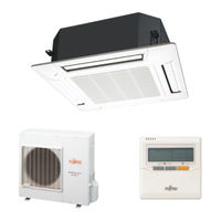
Fujitsu AR*G45LMLA Series Design & Technical Manual (356 pages)
Fujitsu 3 phase type Single / Simultaneous multi system
Brand:
Fujitsu
| Category:
Air Conditioner
| Size: 36.74 MB
Table of Contents
Section 1
4
Air Conditioner
1
Table of Contents
4
1 Features of System
5
Performance and Energy Saving
5
Easy Installation
7
Quiet Operation
8
Simultaneous Multi System
9
Control System
10
Group Control
12
2 Model Line up
13
Indoor Units
13
Outdoor Unit
14
Controller
15
Branch Pipes
16
Cassette Grille
17
OTHERS (Optional Parts)
18
Indoor Unit (Single
23
Section 2
24
1 Features
26
Cassette Type
26
Economy Operation
27
Auto Restart
28
Duct Type
29
High Static Pressure Duct Type
31
Ceiling Type
33
2 Remote Controller
35
Wired Remote Controller
35
System Diagram
37
Wiring Specifications
38
Wireless Remote Controller
39
Program Timer
39
Cassette Type
43
Duct Type
45
High Static Pressure Duct Type
47
Ceiling Type
48
4 Dimensions
50
Cassette Type
50
Duct Type
52
High Static Pressure Duct Type
54
Ceiling Type
56
5 Wiring Diagrams
58
Cassette Type
58
Duct Type
59
High Static Pressure Duct Type
60
Ceiling Type
61
Cooling Capacity
62
Cassette Type
62
Duct Type
63
High Static Pressure Duct Type
64
Ceiling Type
65
Heating Capacity
66
Cassette Type
66
Duct Type
67
High Static Pressure Duct Type
68
Ceiling Type
69
7 Fan Performance (and Capacity*)
70
Cassette Type
70
7-1-1. Air Velocity Distribution
70
Air Flow
77
Fresh Air
81
Duct Connection
82
Duct Type
84
Normal Mode
84
High Static Pressure Mode 1
86
High Static Pressure Mode 2
88
High Static Pressure Mode 3
90
High Static Pressure Duct Type
92
Ceiling Type
94
7-4-1. Air Velocity Distribution
94
Air Flow
97
Fresh Air Characteristic
100
8 Operation Noise
101
Noise Level Curve
101
Cassette Type
101
8-1-2. Duct Type
103
8-1-3. High Static Pressure Duct Type
104
Ceiling Type
105
Sound Level Check Point
107
9 Electric Characteristics
109
10 Safety Devices
110
Indoor Unit (Simultaneous Multi
111
Section 3
112
1 Features
114
Compact Cassette Type
114
Slim Duct Type
117
Duct Type
119
Energy Saving
119
Floor / Ceiling Type
121
2 Remote Controller
123
Wired Remote Controller
123
Wireless Remote Controller
127
Sleep Timer
127
3 Specifications
132
Compact Cassette Type
132
Slim Duct Type
133
Duct Type
134
4 Dimensions
136
Compact Cassette Type
136
Slim Duct Type
138
Duct Type
141
5 Wiring Diagrams
145
Compact Cassette Type
145
Slim Duct Type
146
Duct Type
147
Floor / Ceiling Type
148
Cooling Capacity of Simultaneous Multi (Twin)
149
Compact Cassette Type
149
Slim Duct Type
150
Duct Type
151
Floor / Ceiling Type
152
Heating Capacity of Simultaneous Multi (Twin)
153
Compact Cassette Type
153
Slim Duct Type
154
Duct Type
155
Floor / Ceiling Type
156
Cooling Capacity of Simultaneous Multi (Triple)
157
Compact Cassette Type
157
Slim Duct Type
158
Floor / Ceiling Type
159
Heating Capacity of Simultaneous Multi (Triple)
160
Compact Cassette Type
160
Slim Duct Type
161
Floor / Ceiling Type
162
7 Fan Performance
163
Compact Cassette Type
163
7-1-1. Air Velocity Distribution
163
Air Flow
169
SLIM DUCT TYPE with Auto Louver Grille Kit
175
Air Velocity and Temperature Distribution
175
Fan Performance Curve
177
Air Flow
179
Duct Type
180
Fan Performance and Capacity
180
Floor / Ceiling Type
188
Air Velocity Distribution
188
Air Flow
194
8 Operation Noise
197
Noise Level Curve
197
Compact Cassette Type
197
Slim Duct Type
199
Duct Type
200
Floor / Ceiling Type
201
Sound Level Check Point
203
9 Electric Characteristics
206
10 Safety Devices
207
Section 4
209
1 Specifications
210
2 Dimensions
211
Installation Place
212
Single Outdoor Unit Installation
212
Multiple Outdoor Unit Installation
213
Outdoor Unit Installation in Multi Row
213
3 Refrigerant Circuit
214
Single
214
Simultaneous Multi (Twin)
215
Simultaneous Operation Multi (Triple)
216
4 Wiring Diagrams
217
5 Capacity Compensation Rate for Pipe Length and Height Difference
218
6 Air Flow
221
7 Operation Noise
222
Noise Level Curve
222
Sound Level Check Point
224
8 Electric Characteristics
225
9 Safety Devices
226
System Design
227
Section 5
228
1 Pipe Design
230
Important Items When Using Refrigerant (R410A)
230
Limitation
231
Pipe Length
233
Pipe Size
234
Selection of Pipe Heat Insulating Material
236
Additional Charge Calculation
237
2 Piping Connection
240
Caution of Piping
240
Piping to Outdoor Unit
242
Flare Connection
243
Pipe Connection
244
Branch Pipes
246
Installation Work
246
Selection Procedure
246
3 Wiring Design
249
Electrical Wiring
249
Power Supply Cable Wiring
251
Wiring Method
254
Control Patterns
256
Connection Examples
259
4 System Setting
261
Indoor Unit Setting
261
5 External Input & Output
263
Outdoor Unit
263
External Input
263
Low Noise Mode
263
External Output
265
Indoor Unit
267
External Input
268
External Output
270
6 Function Setting Outdoor Unit
273
Field Setting Switches
273
Setting Method
275
Main Pcb
277
Indoor Unit (Setting by Printed Circuit Board)
277
Rotary Switch Setting
278
INDOOR UNIT (Setting by Wireless Remote Controller)
280
INDOOR UNIT (Setting by Wired Remote Controller)
286
Model: Uty-Rnn
287
Model: Uty-Rvn
290
INDOOR UNIT (Setting by Simple Remote Controller)
293
Function Details
297
Wired Remote Controller
302
Model: Uty-Rnn
302
Dip Switch Setting
305
Model: Uty-Rvn
305
Simple Remote Controller
306
7 Optional Parts Installation
309
Drain Pump Unit
309
Duct Type
309
Ceiling Type
312
Fresh Air Intake Kit
313
Cassette Type
313
Installation Location
315
Connection Diagram
318
Accessory Parts
319
Mounting of Indoor Unit
320
Compact Cassette Type
325
Auto Louver Grille Kit
336
8 Installation Precautions
341
Indoor Unit Installation Precautions
341
Outdoor Unit Installation Precautions
344
Heat Insulation
347
Advertisement
Fujitsu AR*G45LMLA Series Service Instruction (102 pages)
3 PHASE TYPE ROOM AIR CONDITIONER
Brand:
Fujitsu
| Category:
Air Conditioner
| Size: 2.19 MB
Table of Contents
Table of Contents
2
Description of each Control Operation
5
Cooling Capacity Control
6
Cooling Operation
6
Heating Capacity Control
7
Compressor Frequency Range
7
Heating Operation
7
Indoor Unit Control
8
Compressor Control Based on Room Temperature
8
Indoor Fan Control for AC Indoor Unit
8
Dry Operation
8
Operation Mode Selection Table
9
Auto Changeover Operation
9
Auto Changeover Operation Flow Chart
10
Fan Speed
11
Indoor Fan Control
11
Fan Operation
13
Cooling Operation
13
Heating Operation
13
Cool Air Prevention Control
14
Duct Type
14
High Static Duct Type
14
Outdoor Fan Motor
15
Fan Speed of the Outdoor Unit
15
Outdoor Fan Control
15
Swing Operation
16
Vertical Louver Control
16
Louver Control
16
Horizontal Louver Control
17
Air Direction Range
17
Operation Frequency Range
22
Operation Frequency Control at Start up
22
Compressor Control
22
Timer Operation Control
23
Wireless Remote Controller
23
On / off Timer
23
Program Timer
23
Sleep Timer
24
In the Cooling Operation Mode
24
In the Heating Operation Mode
24
Wired Remote Controller
25
Weekly Timer
25
Day off Setting
26
Temperature Set Back Timer
26
Pulse Range of EEV
27
Electronic Expansion Valve Control
27
Test Operation Control
27
Prevent to Restart for 3 Minutes
27
4-Way Valve Extension Select
28
Auto Restart
28
Manual Auto Operation
28
Pump down
29
Condition of the Defrost Operation Completion
30
Compressor Preheating
30
Defrost Operation Control
30
Defrost Flow Chart
31
Off Defrost Operation Condition
32
Off Defrost End Condition
32
OFF Defrost Flow Chart
32
Off Defrost Operation Control
32
10C Heat Operation
33
Discharge Gas Temperature over Rise Prevention Control
33
Economy Operation
33
Various Protections
33
Low Pressure Protection Control
34
Pressure over Rise Protection
34
Anti Freezing Protection
34
Heating Overload Protection
35
High Temperature Release Control
35
Current Release Control
35
Compressor Stop Control
36
Forced Cooling Operation
36
Fresh Air Control
36
External Electrical Heater Control
36
During Heating / Fan Mode / Stop Operation
37
Float Switch Turns off Less than 3 Minutes
37
During Cooling / Dry Mode
37
Drain Pump Operation
37
Low Noise Operation
38
Peak Cut Operation
38
Description of Display Unit
39
Layout of Display Unit
39
Display Mode
40
Display Pattern
40
Procedure for Present Value
40
Detail of LED Display Data
41
Error History Mode
43
Procedure for History Mode
43
Error Code
43
Error Check Mode
44
Procedure for Error Check Mode
44
Demand Response Operation
44
Error Display
46
Indoor Unit and Wired Remote Controller Display
46
Error Code History Display
47
Wired Remote Controller Display
47
Reset the Power and Operate
48
Check Connection
48
Check the Voltage of Power Supply
48
Trouble Shooting with Error Code
48
Trouble Shooting with no Error Code
79
Service Parts Information
84
Inverter Compressor
85
Outdoor Unit Electronic Expansion Valve
86
Indoor Unit Fan Motor
87
Outdoor Unit Fan Motor
88
Disassembly Process
90
SERVICE PANEL Removal
90
INSULATION SHEET Removal
90
Main PCB Removal
91
Inverter, PFC, Filter and Capacitor PCB Removal
91
Filter PCB Removal
92
PFC PCB Removal
92
Inverter PCB Removal
92
CAPACITOR PCB Removal
93
Fan Motor Removal
94
Top Panel Removal
95
Pipe Cover Front Removal
95
Right Panel Removal
95
Reactor Removal
96
Thermistor Removal
96
Solenoid Coil Removal
96
EEV Coil Removal
97
Pressure Sensor Removal
97
Compressor Removal
98
Precautions for Exchange of Refrigerant-Cycle-Parts
100
Advertisement
Related Products
Fujitsu AR*G45LHTA Series
Fujitsu ARG45TLC3
Fujitsu ARG45ALC3
Fujitsu ARG45RLC3
Fujitsu ARG45FUAN
Fujitsu ARG45UUAN
Fujitsu ARG45ELC3
Fujitsu AR*G24LMLAX2
Fujitsu AR*G18LVTBX2
Fujitsu AR*G18LLTA
Fujitsu Categories
Air Conditioner
Laptop
Server
Scanner
Storage
More Fujitsu Manuals
Login
Sign In
OR
Sign in with Facebook
Sign in with Google
Upload manual
Upload from disk
Upload from URL