Sign In
Upload
Manuals
Brands
Cisco Manuals
Network Router
Catalyst 8540 MSR
Cisco Catalyst 8540 MSR Manuals
Manuals and User Guides for Cisco Catalyst 8540 MSR. We have
2
Cisco Catalyst 8540 MSR manuals available for free PDF download: Configuration Manual, Regulatory Compliance And Safety Information Manual
Cisco Catalyst 8540 MSR Configuration Manual (934 pages)
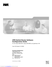
ATM Switch Router Software Configuration Guide
Brand:
Cisco
| Category:
Network Router
| Size: 11.56 MB
Table of Contents
Table of Contents
3
New and Changed Information
31
Related Documentation
33
Document Conventions
34
Obtaining Documentation
35
Ordering Documentation
36
Documentation Feedback
36
Obtaining Technical Assistance
36
Cisco Technical Support Website
36
Submitting a Service Request
37
Definitions of Service Request Severity
37
Obtaining Additional Publications and Information
37
Layer 3 Enabled ATM Switch Router Hardware Overview
39
Chapter 1 Product Overview
40
Available Hardware Components (Catalyst 8540 MSR)
40
Layer 3 Enabled ATM Switch Router Hardware (Catalyst 8510 MSR and Lightstream 1010)
41
Processor and Feature Card Models (Catalyst 8510 MSR and Lightstream 1010)
41
Available Physical Interfaces (Catalyst 8510 MSR and Lightstream 1010)
42
Summary of Software Features
43
System Availability (Catalyst 8540 MSR)
43
ATM Addressing and Plug-And-Play Operation
44
Connections
44
Resource Management
45
Signalling and Routing
45
ATM Internetworking Services (Catalyst 8510 MSR and Lightstream 1010)
46
Network Clocking
46
Management and Monitoring
46
Available Network Management Applications
47
Layer 3 Features
48
Chapter 2 Understanding the User Interface
49
User Interface Overview
49
Accessing each Command Mode
50
EXEC Mode
53
Privileged EXEC Mode
54
ROM Monitor Mode
54
Global Configuration Mode
54
Interface Configuration Mode
55
Interface Range Configuration Mode
56
Subinterface Configuration Mode
57
Line Configuration Mode (Catalyst 8540 MSR)
57
Line Configuration Mode (Catalyst 8510 MSR and Lightstream 1010)
58
Map-List Configuration Mode
58
Map-Class Configuration Mode
59
ATM Router Configuration Mode
59
PNNI Node Configuration Mode
60
PNNI Explicit Path Configuration Mode
60
ATM Accounting File Configuration Mode
61
ATM Accounting Selection Configuration Mode
61
LANE Configuration Server Database Configuration Mode
62
ATM E.164 Translation Table Configuration Mode
62
ATM Signalling Diagnostics Configuration Mode
63
Controller Configuration Mode
63
Redundancy Configuration Mode (Catalyst 8540 MSR)
64
Main CPU Configuration Mode (Catalyst 8540 MSR)
64
Additional Cisco IOS CLI Features
65
About Embedded Ciscoview
65
Installing and Configuring Embedded Ciscoview
65
Displaying Embedded Ciscoview Information
68
CHAPTER 3 Initially Configuring the ATM Switch Router
70
Methods for Configuring the ATM Switch Router
70
Terminal Line Configuration (Catalyst 8540 MSR)
70
Terminal Line Configuration (Catalyst 8510 MSR and Lightstream 1010)
70
Configuration Prerequisites
70
Verifying Software and Hardware Installed on the ATM Switch Router
71
Configuring the BOOTP Server
72
Configuring the ATM Address
73
Manually Setting the ATM Address
74
Modifying the Physical Layer Configuration of an ATM Interface
74
Configuring the IP Interface
75
Configuring IP Address and Subnet Mask Bits
76
Displaying the IP Address
76
Testing the Ethernet Connection
77
Configuring Network Clocking
78
Network Clocking Features
78
Configuring Network Clock Sources and Priorities (Catalyst 8540 MSR)
78
Configuring Network Clock Sources and Priorities (Catalyst 8510 MSR and Lightstream 1010)
79
Configuring the Transmit Clocking Source
80
Displaying the Network Clocking Configuration
80
Configuring Network Clocking with NCDP
81
NCDP Network Example
82
Enabling NCDP
83
Configuring Network Clock Sources and Priorities
83
Configuring Optional NCDP Global Parameters
83
Configuring Optional NCDP Per-Interface Parameters
84
Displaying the NCDP Configuration
85
Network Clock Services for CES Operations and CBR Traffic
86
Configuring Network Routing
86
Configuring ATM Static Routes for IISP or PNNI
86
Configuring System Information
87
Configuring Online Diagnostics (Catalyst 8540 MSR)
87
Access Test (Catalyst 8540 MSR)
87
OIR Test (Catalyst 8540 MSR)
88
Snake Test (Catalyst 8540 MSR)
88
Configuring Online Diagnostics (Catalyst 8540 MSR)
89
Displaying the Online Diagnostics Configuration and Results (Catalyst 8540 MSR)
89
Configuring SNMP and RMON
91
Testing the Configuration
92
Confirming the Hardware Configuration (Catalyst 8540 MSR)
93
Confirming the Hardware Configuration (Catalyst 8510 MSR and Lightstream 1010)
93
Confirming the Software Version
94
Confirming Power-On Diagnostics
94
Confirming the Ethernet Configuration
96
Confirming the ATM Address
96
Testing the Ethernet Connection
97
Confirming the ATM Connections
97
Confirming the ATM Interface Configuration
98
Confirming the Interface Status
98
Confirming Virtual Channel Connections
99
Confirming the Running Configuration
100
Confirming the Saved Configuration
101
CHAPTER 4 Configuring System Management Functions
103
System Management Tasks
103
C H a P T E R 4 Configuring System Management Functions
104
Configuring Alias
104
Configuring Buffers
104
Configuring Terminal Lines and Modem Support (Catalyst 8510 MSR and Lightstream 1010)
104
Configuring Terminal Lines and Modem Support (Catalyst 8540 MSR)
104
Configuring Cisco Discovery Protocol
105
Configuring Enable Passwords
106
Configuring Load Statistics Interval
106
Configuring Logging
106
Configuring Login Authentication
107
Configuring Scheduler Attributes
108
Configuring Services
108
Configuring SNMP
109
Username Commands
110
Configuring the Privilege Level
111
Configuring Privilege Level (Global)
111
Configuring Privilege Level (Line)
111
Configuring the Network Time Protocol
112
Displaying the NTP Configuration
114
Configuring the Clock and Calendar
115
Configuring the Clock
115
Configuring the Calendar
116
Configuring TACACS
116
Configuring AAA Access Control with TACACS
117
Configuring AAA Accounting
118
Configuring TACACS Server
118
Configuring PPP Authentication
118
Configuring RADIUS
118
Configuring RADIUS Authentication
119
Configuring RADIUS Authorization
119
Configuring RADIUS Servers
119
Configuring RADIUS Server Communication
120
Configuring Secure Shell
121
Displaying and Disconnecting SSH
124
Testing the System Management Functions
125
Displaying Active Processes
125
Displaying Protocols
125
Displaying Stacks
125
Displaying Routes
126
Displaying Environment
126
Checking Basic Connectivity (Catalyst 8540 MSR)
126
Checking Basic Connectivity (Catalyst 8510 MSR and Lightstream 1010)
126
Route Processor Redundant Operation (Catalyst 8540 MSR)
127
Chapter 5 Configuring Redundancy
128
Configuring Route Processor Redundancy (Catalyst 8540 MSR)
129
Forcing a Route Processor Switchover (Catalyst 8540 MSR)
129
Displaying the Configuration Register Value
131
Synchronizing the Configurations (Catalyst 8540 MSR)
131
Immediately Synchronizing Route Processor Configurations (Catalyst 8540 MSR)
132
Immediately Synchronizing Route Processor Counters (Catalyst 8540 MSR)
132
Synchronizing the Configurations During Switchover (Catalyst 8540 MSR)
132
Synchronizing the Dynamic Information (Catalyst 8540 MSR)
133
Configuring Dynamic Information Synchronization (Catalyst 8540 MSR)
133
Configuring Counter Synchronization (Catalyst 8540 MSR)
134
Displaying the Route Processor Redundancy Configuration (Catalyst 8540 MSR)
135
Preparing a Route Processor for Removal (Catalyst 8540 MSR)
136
Configuring Switch Fabric Enhanced High System Availability Operation (Catalyst 8540 MSR)
137
Configuring Preferred Switching Processors (Catalyst 8540 MSR)
138
Displaying the Preferred Switch Processor Redundancy Configuration (Catalyst 8540 MSR)
138
Displaying the Switch Processor EHSA Configuration (Catalyst 8540 MSR)
139
Storing the Configuration
140
Chapter 6 Configuring ATM Network Interfaces
141
Disabling Autoconfiguration
141
Displaying the Autoconfiguration
142
Configuring UNI Interfaces
143
Displaying the UNI Interface Configuration
143
Configuring NNI Interfaces
144
Displaying the NNI Interface Configuration
144
Configuring a 12-Bit VPI NNI Interface (Catalyst 8540 MSR)
145
Displaying the 12-Bit VPI NNI Interface Configuration (Catalyst 8540 MSR)
146
Configuring IISP Interfaces
147
Displaying the IISP Configuration
148
CHAPTER 7 Configuring Virtual Connections
150
Characteristics and Types of Virtual Connections
150
Configuring Virtual Channel Connections
150
Displaying Vccs
152
Deleting Vccs from an Interface
154
Configuring Terminating PVC Connections
156
Displaying the Terminating PVC Connections
158
Configuring PVP Connections
158
Displaying PVP Configuration
159
Deleting Pvps from an Interface
161
Confirming PVP Deletion
161
Configuring Point-To-Multipoint PVC Connections
162
Displaying Point-To-Multipoint PVC Configuration
163
Configuring Point-To-Multipoint PVP Connections
165
Displaying Point-To-Multipoint PVP Configuration
166
Configuring Soft PVC Connections
167
Guidelines for Creating Soft Pvcs
168
Configuring Soft Pvcs
168
Displaying Soft PVC Configuration
170
Modifying CTTR Indexes on an Existing Soft PVC
172
Configuring Soft PVP Connections
174
Displaying Soft PVP Connections
175
Modifying CTTR Indexes on an Existing Soft PVP
176
Configuring the Soft PVP or Soft PVC Route Optimization Feature
177
Enabling Soft PVP or Soft PVC Route Optimization
177
Displaying an Interface Route Optimization Configuration
178
Configuring Soft Pvcs with Explicit Paths
179
Changing Explicit Paths for an Existing Soft PVC
179
Displaying Explicit Path for Soft PVC Connections
180
Configuring Soft Pvcs and Soft Pvps with Priority
182
Configuring a Soft PVC with Priority
182
Configuring a Soft PVP with Priority
183
Configuring a Soft PVC with Priority for a CES Circuit
183
Configuring a Soft PVC with Priority for Frame Relay Connections
183
Configuring Two-Ended Soft PVC and Soft PVP Connections
186
Configuring Two-Ended Soft PVC Connections
187
Configuring Two-Ended Soft PVP Connections
188
Configuring Access Filters on Soft PVC and Soft PVP Passive Connections
190
Configuring Access Filters on Soft PVC Passive Connections
191
Configuring Access Filters on Soft PVP Passive Connections
195
Configuring Timer Rules Based Soft PVC and Soft PVP Connections
198
Configuring Timer Rules Based Soft Pvcs
199
Configuring Timer Rules Based Soft Pvps
200
Displaying the Timer Rules Based Soft PVC and Soft PVP Configuration
201
Configuring Backup Addresses for Soft PVC and Soft PVP Connections
203
How Redundant Soft VC Destinations Work
203
Redundant Soft VC Destinations on the same Switch
203
Redundant Soft VC Destinations on Different Switches
205
Configuring Redundant Soft VC Destinations
207
Displaying the Redundant Soft VC Destination Address Configuration
209
Configuring Point-To-Multipoint Soft PVC Connections
211
Guidelines for Creating Point-To-Multipoint Soft Pvcs
212
Configuring Point-To-Multipoint Soft Pvcs
213
Configuration Mode
214
Displaying Point-To-Multipoint Soft PVC Configuration
215
Configuring Traffic Parameters for Point-To-Multipoint Soft-PVC Connections
216
Enabling and Disabling the Root of a Point-To-Multipoint Soft-PVC Connections
217
Enabling and Disabling a Leaf of a Point-To-Multipoint Soft PVC
218
Confirming the Party Leaf Is Disabled or Enabled
219
Configuring the Retry Interval for Point-To-Multipoint Soft-PVC Parties
220
Deleting a Point-To-Multipoint Soft PVC
220
Confirming VCC Deletion
221
Configuring Nondefault Well-Known Pvcs
222
Overview of Nondefault PVC Configuration
222
Configuring Nondefault Pvcs
223
Configuring a VPI/VCI Range for Svps and Svcs
224
Configuring VP Tunnels
227
Configuring a VP Tunnel for a Single Service Category
228
Displaying the VP Tunnel Configuration
229
Configuring a Shaped VP Tunnel
229
Configuring a Shaped VP Tunnel on an Interface
230
Displaying the Shaped VP Tunnel Configuration
231
Configuring a Hierarchical VP Tunnel for Multiple Service Categories
231
Enabling Hierarchical Mode
232
Displaying the Hierarchical VP Tunnel Configuration
233
Configuring an End-Point PVC to a PVP Tunnel
234
Displaying Pvcs
235
Configuring Signalling VPCI for VP Tunnels
235
Displaying the VP Tunnel VPCI Configuration
236
Deleting VP Tunnels
236
Confirming VP Tunnel Deletion
236
Configuring Interface and Connection Snooping
237
Snooping Test Ports (Catalyst 8510 MSR and Lightstream 1010)
238
Effect of Snooping on Monitored Port
238
Shutting down Test Port for Snoop Mode Configuration
238
Other Configuration Options for Snoop Test Port
239
Configuring Interface Snooping
239
Displaying Interface Snooping
239
Configuring Per-Connection Snooping
240
Displaying Per-Connection Snooping
241
Input Translation Table Management
243
Feature Overview
243
VC Block Allocation
244
Freeing an ITT Block
244
Growing an ITT Block
244
ITT Fragmentation
244
Benefits
244
Reducing ITT Fragmentation
245
System and Startup ITT Fragmentation
245
Solution: Minimum Block-Size Per-VPI
245
Using the Minblock Command to Specify a Minimum Block Size
245
Using the Autominblock Command to Enable the Minimum Mode
246
Shrinking ITT Block Size
248
Displaying ITT Resources
248
Configuration Examples
249
Chapter 8 Configuring Operation, Administration, and Maintenance
255
OAM Overview
255
Configuring OAM Functions
257
Configuring OAM for the Entire Switch (Catalyst 8540 MSR)
257
Configuring OAM for the Entire Switch (Catalyst 8510 MSR and Lightstream 1010)
257
Configuring the Interface-Level OAM
258
Checking the ATM Connection (Catalyst 8540 MSR)
259
Checking the ATM Connection (Catalyst 8510 MSR and Lightstream 1010)
259
Displaying the OAM Configuration
260
Chapter 9 Configuring Resource Management
263
Resource Management Functions
264
Switch Fabric Functionality (Catalyst 8540 MSR)
264
Processor Feature Card Functionality (Catalyst 8510 MSR and Lightstream 1010)
265
Configuring Global Resource Management
266
Configuring the Default Qos Objective Table
267
Displaying the ATM Qos Objective Table
268
Configuring the Switch Oversubscription Factor (Catalyst 8510 MSR and Lightstream 1010)
268
Displaying the OSF Configuration (Catalyst 8510 MSR and Lightstream 1010)
269
Configuring the Service Category Limit (Catalyst 8510 MSR and Lightstream 1010)
269
Displaying the Service Category Limit Configuration (Catalyst 8510 MSR and Lightstream 1010)
270
Configuring the ABR Congestion Notification Mode (Catalyst 8510 MSR and Lightstream 1010)
270
Displaying the ABR Congestion Notification Mode Configuration (Catalyst 8510 MSR and Lightstream 1010)
271
Configuring the Connection Traffic Table
272
CTT Supported Features (Catalyst 8540 MSR)
272
CTT Supported Features (Catalyst 8510 MSR and Lightstream 1010)
272
PVC Connection Traffic Rows
273
SVC Connection Traffic Rows
273
CTT Row Allocations and Defaults
273
Displaying the ATM Connection Traffic Table
274
Configuring the Sustainable Cell Rate Margin Factor
275
Displaying the SCR Margin Configuration
275
Overview of Threshold Groups
276
Configuring the Threshold Group
277
Displaying the Threshold Group Configuration
278
Configuring Physical Interfaces
279
Configuring the Interface Maximum Queue Size (Catalyst 8510 MSR and Lightstream 1010)
279
Displaying the Output Queue Maximum Configuration (Catalyst 8510 MSR and Lightstream 1010)
280
Configuring the Interface Queue Thresholds Per Service Category (Catalyst 8510 MSR and Lightstream 1010)
281
Configuring Interface Output Pacing
283
Displaying the Output Pacing Configuration
284
Configuring Controlled Link Sharing
284
Displaying the Controlled Link Sharing Configuration
285
Configuring the Scheduler and Service Class
286
Displaying the Interface Service Class Information
287
Configuring Physical and Logical Interface Parameters
288
Configuring the Interface Link Distance
288
Displaying the Interface Link Distance Configuration
288
Configuring the Limits of Best-Effort Connections
289
Displaying the Interface Best-Effort Limit Configuration
290
Configuring the Interface Maximum of Individual Traffic Parameters
291
Displaying the Interface Maximum Individual Traffic Parameter Configuration
292
Configuring the ATM Default CDVT and MBS
293
Displaying the ATM CDVT and MBS Configuration
293
Configuring Interface Service Category Support
295
Displaying the Service Category on an Interface
296
Configuring SVC Policing by Service Category
297
Displaying the Service Category Policing on an Interface
298
Configuring Interface Overbooking
299
Displaying the Interface Overbooking Configuration
300
Configuring Service Class Overbooking
301
Displaying the Interface Overbooking Configuration
302
Configuring Framing Overhead
303
Displaying the Framing Overhead Configuration
304
Configuring the Global ILMI System
307
Configuring the ATM Address
307
Chapter 10 Configuring ILMI
308
Configuring Global ILMI Access Filters
308
Display the ILMI Access Filter Configuration
309
Configuring the LANE Configuration Server Address
309
Displaying the ILMI Global Configuration
310
Configuring an ILMI Interface
311
Configuring Per-Interface ILMI Address Prefixes
312
Displaying ILMI Address Prefix
312
Displaying the ILMI Interface Configuration
314
Configuring ATM Address Groups
314
Displaying ATM Address Group Configuration
315
Overview
317
Chapter 11 Configuring ATM Routing and PNNI
318
ATM Addresses
318
IISP Configuration
318
Configuring the Routing Mode
318
Displaying the ATM Routing Mode Configuration
319
Configuring the ATM Address
320
Displaying the ATM Address Configuration
321
Configuring Static Routes
322
Displaying the Static Route Configuration
322
Configuring ATM Address Groups
323
Displaying ATM Address Group Configuration
324
Basic PNNI Configuration
325
Configuring PNNI Without Hierarchy
325
Configuring the Lowest Level of the PNNI Hierarchy
325
Configuring an ATM Address and PNNI Node Level
325
Configuring Static Routes
327
Configuring a Summary Address
329
Configuring Scope Mapping
330
Configuring Higher Levels of the PNNI Hierarchy
332
Configuring a Logical Group Node and Peer Group Identifier
332
Configuring the Node Name
334
Configuring a Parent Node
335
Configuring the Node Election Leadership Priority
336
Configuring a Summary Address
338
PNNI Hierarchy Configuration Example
340
Advanced PNNI Configuration
345
Tuning Route Selection
345
Configuring Background Route Computation
345
Configuring Link Selection
347
Configuring the Maximum Administrative Weight Percentage
349
Configuring the Precedence
350
Configuring Explicit Paths
352
Tuning Topology Attributes
355
Configuring the Global Administrative Weight Mode
355
Configuring Administrative Weight Per Interface
356
Configuring Transit Restriction
357
Configuring Redistribution
358
Configuring Aggregation Token
359
Configuring Aggregation Mode
361
Configuring Significant Change Thresholds
362
Configuring the Complex Node Representation for Lgns
364
Tuning Protocol Parameters
365
Configuring PNNI Hello, Database Synchronization, and Flooding Parameters
365
Configuring the Resource Management Poll Interval
367
Configuring ATM PNNI Statistics Collection
368
Displaying ATM PNNI Statistics
369
Mobile PNNI Configuration
369
Connecting Mobile PNNI Networks to Fixed PNNI Networks
370
Configuring a Mobile PNNI Interface
370
Configuring Mobile PNNI Nodes
370
Displaying Mobile PNNI Operational Details
372
Configuring a Limit for the ONHL
373
PNNI Connection Trace
373
Initiating a Connection Trace
374
Displaying the Connection Trace Output
377
Displaying PNNI Connection Trace Configuration
380
Deleting Connection Trace Requests
380
Designating PNNI Trace Boundaries
381
Access Control Overview
383
Configuring a Template Alias
384
Chapter 12 Using Acces Control
385
Displaying the Template Alias Configuration
385
Configuring ATM Filter Sets
385
Deleting Filter Sets
387
Configuring an ATM Filter Expression
387
Configuring ATM Interface Access Control
388
Displaying ATM Filter Configuration
389
ATM Filter Configuration Scenario
390
Filtering IP Packets at the IP Interfaces
391
Creating Standard and Extended IP Access Lists
391
Applying an IP Access List to an Interface or Terminal Line
393
IP Access List Examples
394
Examples of Implicit Masks in IP Access Lists
394
Examples of Configuring Extended IP Access Lists
394
Configuring Per-Interface Address Registration with Optional Access Filters
395
Displaying the ILMI Access Filter Configuration
396
Configuring Classical IP over ATM
397
Configuring Classical IP over ATM in an SVC Environment
397
Chapter 13 Configuring IP over ATM
398
Configuring as an ATM ARP Client
398
Configuring as an ATM ARP Server
400
Configuring Classical IP over ATM in a PVC Environment
401
Displaying the IP-Over-ATM Interface Configuration
401
Displaying the IP-Over-ATM Interface Configuration
402
Mapping a Protocol Address to a PVC Using Static Map Lists
403
Configuring a PVC-Based Map List
403
Displaying the Map-List Interface Configuration
405
Configuring an SVC-Based Map List
405
Displaying the Map-List Interface Configuration
406
Policy-Based Routing
407
Policy-Based Routing Restrictions
407
Configuring IP Load Sharing
409
Configuring TCP Packet Load Sharing
409
Configuring Packet Load Sharing for All IP Traffic
409
LANE Functionality and Requirements
411
Chapter 14 Configuring LAN Emulation
412
LANE Router and Switch Router Requirements
412
LANE Configuration Tasks
412
Creating a LANE Plan and Worksheet
413
Automatic ATM Addressing and Address Templates for LANE Components
413
Rules for Assigning Components to Interfaces and Subinterfaces
414
Example LANE Plan and Worksheet
415
Displaying LANE Default Addresses
416
Entering the ATM Address of the Configuration Server
417
Setting up the Configuration Server Database
417
Setting up the Database for the Default Emulated LAN Only
417
Setting up the Database for Unrestricted-Membership Emulated Lans
418
Setting up the Database for Restricted-Membership Emulated Lans
419
Enabling the Configuration Server
420
Setting up Less and Clients
421
Setting up the Server, BUS, and a Client on a Subinterface
422
Setting up a Client on a Subinterface
422
Configuring a LAN Emulation Client on the ATM Switch Router
423
Configuring an Ethernet LANE Client
424
Configuring Fault-Tolerant Operation
425
Enabling Redundant Lecss and Les/Buss
425
Monitoring and Maintaining the LANE Components
426
LANE Configuration Examples
427
Default Configuration for a Single Emulated LAN
427
Ethernet Example
428
Confirming Connectivity between the ATM Switch and Other LANE Members
431
Token Ring Example (Catalyst 8510 MSR and Lightstream 1010)
433
Confirming Connectivity between the ATM Switch and the Routers
434
Displaying the LANE Client Configuration on the ATM Switch
435
Default Configuration for a Single Emulated LAN with Backup LECS and LES on the ATM Switch Router
435
Ethernet Example
436
Token Ring Example (Catalyst 8510 MSR and Lightstream 1010)
438
Displaying the LECS Configuration on the ATM Switch Router
440
Displaying the LES Configuration on the ATM Switch Router
440
Default Configuration for a Token Ring ELAN with IP Source Routing (Catalyst 8510 MSR and Lightstream 1010)
441
Configuring ATM Accounting
443
ATM Accounting Overview
444
C H a P T E R 15 Configuring ATM Accounting, RMON, and SNMP
444
Configuring Global ATM Accounting
445
Displaying the ATM Accounting Configuration
445
Enabling ATM Accounting on an Interface
446
Displaying the ATM Accounting Interface Configuration
446
Configuring the ATM Accounting Selection Table
447
Displaying ATM Accounting Selection Configuration
448
Configuring ATM Accounting Files
449
Displaying the ATM Accounting File Configuration
450
Controlling ATM Accounting Data Collection
451
Displaying the ATM Accounting Data Collection Configuration and Status
451
Configuring ATM Accounting SNMP Traps
452
Configuring ATM Accounting Trap Generation
452
Displaying ATM Accounting Trap Threshold Configuration
452
Configuring SNMP Server for ATM Accounting
453
Displaying SNMP Server ATM Accounting Configuration
453
Using TFTP to Copy the ATM Accounting File
454
Configuring Remote Logging of ATM Accounting Records
455
Displaying the Remote Logging Configuration
455
Configuring ATM RMON
456
RMON Overview
456
Configuring Port Select Groups
457
Displaying the ATM RMON Port Select Group
458
Configuring Interfaces into a Port Select Group
458
Displaying the Interface Port Selection Group Configuration
458
Enabling ATM RMON Data Collection
459
Displaying the ATM RMON Configuration
460
Configuring an RMON Event
460
Displaying the Generated RMON Events
461
Configuring an RMON Alarm
461
Displaying the Generated RMON Alarms
461
SNMP Overview
462
Configuring SNMP
462
Configuring SNMP-Server Hosts
463
Configuring SNMP Traps
463
Configuring Interface Index Persistence
465
SNMP Examples
465
Displaying the SNMP Configuration
465
Tag Switching Overview
467
Chapter 16 Configuring Tag Switching and MPL
468
Hardware and Software Requirements and Restrictions (Catalyst 8510 MSR and Lightstream 1010)
468
Configuring Tag Switching
468
Configuring a Loopback Interface
469
Displaying Loopback Interface Configuration
469
Enabling Tag Switching on the ATM Interface
470
Displaying the ATM Interface Configuration
471
Configuring OSPF
471
Displaying the OSPF Configuration
472
Configuring a VPI Range (Optional)
472
Displaying the Tag Switching VPI Range
473
Configuring TDP Control Channels (Optional)
474
Displaying the TDP Control Channels
475
Configuring Tag Switching on VP Tunnels
475
Connecting the VP Tunnels
477
Displaying the VP Tunnel Configuration
477
Configuring VC Merge
478
Displaying the VP Tunnel Configuration
478
Displaying the VC Merge Configuration
478
Configuring Tag Switching Cos
479
Configuring the Service Class and Relative Weight
480
Displaying the TVC Configuration
481
Threshold Group for TBR Classes
483
RM CAC Support
484
Tag Switching Configuration Example
485
MPLS Overview
487
Obtaining Additional MPLS Documentation
487
Hardware and Software Restrictions
488
Mpls/Tag Switching Terminology
489
How MPLS Works
490
Distribution of Label Bindings
491
Summary Route Propagation
491
LFIB Table Look up Process
492
MPLS Network Packet Transmission
493
Configuring Label Edge Routing
494
LER Software Limitations
495
MPLS Processing
496
Tag Switching Processing
497
MPLS over Fast Ethernet Interfaces
497
Configuring MPLS on Fast Ethernet Interfaces
498
MPLS Vpns
499
Configuring VPN on Fast Ethernet Interface
500
Fast Ethernet Interface Example
500
Network Configuration Example
501
Configuring MPLS VPN Using ATM RFC 1483 Interfaces
505
Network Configuration Example
506
CHAPTER 17 Configuring Signalling Features 17-1
512
Configuring Signalling IE Forwarding
512
Displaying the Interface Signalling IE Forwarding Configuration
512
C H a P T E R 17 Configuring Signalling Features
513
Configuring ATM SVC Frame Discard
513
Displaying the ATM Frame Discard Configuration
514
Configuring E.164 Addresses
514
E.164 Conversion Methods
515
Configuring E.164 Gateway
515
Configuring an E.164 Address Static Route
516
Displaying the E.164 Static Route Configuration
516
Configuring an ATM E.164 Address on an Interface
516
Displaying the E.164 Address Association to Interface Configuration
517
Configuring E.164 Address Autoconversion
518
Displaying the E.164 Address Autoconversion
519
Configuring E.164 Address One-To-One Translation Table
519
Displaying the ATM E.164 Translation Table Configuration
520
Configuring Signalling Diagnostics Tables
521
Displaying the Signalling Diagnostics Table Configuration
524
Configuring Closed User Group Signalling
525
Configuring Aliases for CUG Interlock Codes
526
Configuring CUG on an Interface
526
Displaying the CUG
527
Displaying the Signalling Statistics
529
Disabling Signalling on an Interface
530
Multipoint-To-Point Funnel Signalling
530
Displaying Multipoint-To-Point Funnel Connections
530
Configuring Interfaces
533
Configuring 25-Mbps Interfaces (Catalyst 8510 MSR and Lightstream 1010)
534
Default 25-Mbps ATM Interface Configuration Without Autoconfiguration (Catalyst 8510 MSR and Lightstream 1010)
534
Chapter 18 Configuring Interface
535
Manual 25-Mbps Interface Configuration (Catalyst 8510 MSR and Lightstream 1010)
535
Configuring 155-Mbps SM, MM, and UTP Interfaces
535
Default 155-Mbps ATM Interface Configuration Without Autoconfiguration
536
Manual 155-Mbps Interface Configuration
536
Configuring OC-3C MMF Interfaces (Catalyst 8540 MSR)
537
Default OC-3C MMF Interface Configuration Without Autoconfiguration (Catalyst 8540 MSR)
537
Manual OC-3C MMF Interface Configuration (Catalyst 8540 MSR)
538
Configuring 622-Mbps SM and MM Interfaces
538
Default 622-Mbps ATM Interface Configuration Without Autoconfiguration
539
Manual 622-Mbps Interface Configuration
540
Configuring OC-12C SM and MM Interfaces (Catalyst 8540 MSR)
541
OC-12C Interface Configuration (Catalyst 8540 MSR)
541
Default OC-12C ATM Interface Configuration Without Autoconfiguration (Catalyst 8540 MSR)
541
Manual OC-12C Interface Configuration (Catalyst 8540 MSR)
542
Configuring OC-48C SM and MM Interfaces (Catalyst 8540 MSR)
543
Default OC-48C ATM Interface Configuration Without Autoconfiguration (Catalyst 8540 MSR)
543
Manual OC-48C Interface Configuration (Catalyst 8540 MSR)
544
Configuring DS3 and E3 Interfaces
545
DS3 and E3 Interface Configuration
545
Default DS3 and E3 ATM Interface Configuration Without Autoconfiguration
545
Manual DS3 and E3 Interface Configuration
546
Configuring T1/E1 Trunk Interfaces
547
T1/E1 Trunk Interface Configuration
547
Default T1 and E1 ATM Interface Configuration Without Autoconfiguration
547
Manual T1 and E1 Interface Configuration
548
Troubleshooting the Interface Configuration
549
C H a P T E R 19 Configuring Circuit Emulation Services
552
CHAPTER 19 Configuring Circuit Emulation Services
552
Overview of CES T1/E1 Interfaces
552
Clocking Options
552
Interfaces Supported
552
Connectors Supported
552
Functions Supported by CES Modules
552
Framing Formats and Line Coding Options for CES Modules
553
Default CES T1/E1 Interface Configuration
553
Configuring CES T1/E1 Interfaces
554
General Guidelines for Creating Soft Pvcs for Circuit Emulation Services
557
Configuring T1/E1 Unstructured Circuit Emulation Services
559
Overview of Unstructured Circuit Emulation Services
559
Configuring Network Clocking for Unstructured CES
560
Configuring a Hard PVC for Unstructured CES
560
Verifying a Hard PVC for Unstructured CES
563
Configuring a Soft PVC for Unstructured CES
563
Phase 1—Configuring the Destination (Passive) Side of the Soft PVC
565
Phase 2—Configuring the Source (Active) Side of the Soft PVC
566
Verifying a Soft PVC for Unstructured CES
567
Configuring T1/E1 Structured (N X 64) Circuit Emulation Services
568
Overview of Structured Circuit Emulation Services
568
Configuring Network Clocking for Structured CES
569
Configuring a Hard PVC for Structured CES
569
Verifying a Hard PVC for Structured CES
572
Configuring a Hard PVC for Structured CES with a Shaped VP Tunnel
573
Phase 1—Configuring a Shaped VP Tunnel
573
Phase 2—Configuring a Hard PVC
575
Verifying a Hard PVC for Structured CES with a Shaped VP Tunnel
577
Configuring a Soft PVC for Structured CES
578
Phase 1—Configuring the Destination (Passive) Side of a Soft PVC
580
Phase 2—Configuring the Source (Active) Side of a Soft PVC
581
Verifying a Soft PVC for Structured CES
583
Configuring a Soft PVC for Structured CES with CAS Enabled
584
Verifying a Soft PVC for Structured CES with CAS Enabled
586
Configuring a Soft PVC for Structured CES with CAS and On-Hook Detection Enabled
587
Verifying a Soft PVC for Structured CES with CAS and On-Hook Detection Enabled
588
Creating Multiple Structured Soft Pvcs on the same CES Port
588
Phase 1—Configuring the Destination (Passive) Side of Multiple Soft Pvcs
590
Phase 2—Configuring the Source (Active) Side of Multiple Soft Pvcs
591
Verifying the Creation of Multiple Structured Soft Pvcs on the same CES Port
592
Configuring T1/E1 CES Svcs
594
Configuring T1/E1 Unstructured CES Svcs
594
Phase 1—Configuring the Destination (Passive) Side of the Unstructured Switched VC
595
Phase 2—Configuring the Source (Active) Side of the Unstructured Switched VC
596
Verifying a Switched VC for Unstructured CES
597
Configuring T1/E1 Structured CES Svcs
598
Phase 1—Configuring the Destination (Passive) Side of the Structured Switched VC
599
Phase 2—Configuring the Source (Active) Side of the Structured Switched VC
601
Verifying a Switched VC for Structured CES
603
Reconfiguring a Previously Established Circuit
604
Deleting a Previously Established Circuit
605
Verifying Deletion of a Previously Established Circuit
606
Configuring SGCP
606
Operation
606
Configuring SGCP on the Entire Switch
607
Displaying SGCP
607
Configuring CES Circuits for SGCP
608
Displaying SGCP Endpoints
609
Displaying SGCP Connections
610
Configuring SGCP Request Handling
610
Configuring Call-Agent Address
610
Shutting down SGCP
611
Configuring Explicit Paths on CES Vcs
611
Configuring CES VC Explicit Paths
612
Displaying CES VC Explicit Path Configuration
613
Configuring Point-To-Multipoint CES Soft PVC Connections
613
Guidelines for Creating Point-To-Multipoint CES Soft Pvcs
614
Configuring Point-To-Multipoint Unstructured CES Soft Pvcs
615
Configuring the Destination Side of a Point-To-Multipoint Unstructured CES Soft PVC
615
Configuring the Source Side of a Point-To-Multipoint Unstructured CES Soft PVC
617
Configuring Point-To-Multipoint Structured CES Soft Pvcs
619
Configuring the Destination Side of a Point-To-Multipoint Structured CES Soft PVC
619
Configuring the Source Side of a Point-To-Multipoint Structured CES Soft PVC
621
Displaying Point-To-Multipoint CES Soft PVC Configuration
622
Deleting and Disabling Point-To-Multipoint CES Soft PVC Connections
624
Deleting Point-To-Multipoint CES Soft PVC
624
Enabling and Disabling the Root of a Point-To-Multipoint CES Soft PVC
625
Confirming VCC Deletion
625
Enabling and Disabling a Leaf of a Point-To-Multipoint CES Soft PVC
626
Confirming the Party Leaf Is Disabled or Enabled
626
Configuring the Retry Interval for Point-To-Multipoint CES Soft-PVC Parties
628
C H a P T E R 20 Configuring Frame Relay to ATM Interworking Port Adapter Interfaces
630
CHAPTER 20 Configuring Frame Relay to ATM Interworkingport Adapter Interfaces
630
Configuring the Channelized DS3 Frame Relay Port Adapter
630
Configuration Guidelines
630
Default CDS3 Frame Relay Port Adapter Interface Configuration
630
Configuring the CDS3 Frame Relay Port Adapter Interface
631
Configuring the T1 Lines on the CDS3 Frame Relay Port Adapter
632
Configuring the Channel Group on the CDS3 Frame Relay Port Adapter
632
Displaying the CDS3 Frame Relay Port Adapter Controller Information
633
Deleting a Channel Group on the CDS3
633
Method One
633
Method Two
634
Configuring the Channelized E1 Frame Relay Port Adapter
635
Default CE1 Frame Relay Port Adapter Interface Configuration
635
Configuring the CE1 Frame Relay Port Adapter Interface
636
Configuring the Channel Group on the CE1 Frame Relay Port Adapter
636
Displaying the CE1 Frame Relay Port Adapter Controller Information
637
Configuring Frame Relay to ATM Interworking Functions
637
Enabling Frame Relay Encapsulation on an Interface
637
Displaying Frame Relay Encapsulation
638
Configuring Frame Relay Serial Interface Type
638
Displaying Frame Relay Interface Configuration
639
Configuring Frame Relay Frame Size for Frame Relay to ATM Interworking
639
Configuring and Using Frame Relay Frame Size
640
Configuring LMI
642
Configuring the LMI Type
643
Displaying LMI Type
643
Configuring the LMI Keepalive Interval
644
Displaying LMI Keepalive Interval
644
Configuring the LMI Polling and Timer Intervals (Optional)
644
Displaying Frame Relay Serial Interface
645
Displaying LMI Statistics
645
Configuring Frame Relay to ATM Resource Management
646
Configuring Frame Relay to ATM Connection Traffic Table Rows
646
PVC Connection Traffic Rows
648
Predefined Rows
649
SVC Connection Traffic Rows
649
Creating a Frame Relay to ATM CTT Row
649
Displaying the Frame Relay to ATM Connection Traffic Table
650
Configuring the Interface Resource Management Tasks
650
Displaying Frame Relay Interface Resources
651
Configuring Frame Relay to ATM Virtual Connections
651
Characteristics and Types of Virtual Connections
652
Configuring Frame Relay PVC Connections
652
Configuration Guidelines
653
Configuring Frame Relay to ATM Network Interworking Pvcs
653
Displaying Frame Relay to ATM Network Interworking Pvcs
654
Configuring Frame Relay to ATM Service Interworking Pvcs
655
Displaying Frame Relay to ATM Service Interworking Pvcs
657
Configuring Terminating Frame Relay to ATM Service Interworking Pvcs
657
Displaying Terminating Frame Relay to ATM Service Interworking Pvcs
658
Configuring Frame Relay Transit Pvcs
659
Configuring Frame Relay Soft PVC Connections
660
Configuration Guidelines
660
Configuring Frame Relay to Frame Relay Network Interworking Soft Pvcs
660
Configuring Frame Relay to ATM Network Interworking Soft Pvcs
663
Configuring Frame Relay to ATM Service Interworking Soft Pvcs
665
Display Frame Relay Interworking Soft Pvcs
667
Modifying CTTR Indexes on an Existing Frame Relay Soft PVC
667
Configuring the Soft PVC Route Optimization Feature
668
Standard Signalling for Frame Relay Soft Pvcs
668
Configuring a Frame Relay Interface with Route Optimization
669
Displaying a Frame Relay Interface Route Optimization Configuration
669
Respecifying Existing Frame Relay to ATM Interworking Soft Pvcs
671
Configuring Overflow Queuing
671
Overflow Queuing Functional Image Requirements
672
Configuring Overflow Queuing on Frame Relay to ATM Pvcs
672
Network Internetworking Pvcs
672
Service Internetworking PVC Connections
673
Configuring Overflow Queuing on Frame Relay to Frame Relay Pvcs
674
Configuring Overflow Queuing on Frame Relay to ATM Soft Pvcs
675
Configuring Overflow Queuing on Frame Relay to Frame Relay Soft Pvcs
676
Displaying Overflow Queuing Configuration at the VC Level
677
Overview of IMA
683
C H a P T E R 21 Configuring IMA Port Adapter Interfaces
685
CHAPTER 21 Configuring IMA Port Adapter Interfaces
685
Configuring the T1/E1 IMA Port Adapter
685
Default T1/E1 IMA Interface Configuration
685
Configuring the T1/E1 IMA Interface
686
Displaying the T1/E1 IMA Interface Configuration
687
Configuring IMA Group Functions
688
Creating an IMA Group Interface
688
Adding an Interface to an Existing IMA Group
690
Displaying the IMA Group Configuration
691
Deleting an Interface from an IMA Group
692
Confirming the Interface Deletion
693
Deleting an IMA Group
693
Confirming the IMA Group Deletion
693
Configuring IMA Group Parameters
695
Configuring IMA Group Minimum Active Links
695
Displaying the IMA Group Minimum Active Links Configuration
695
Configuring IMA Group Interface Clock Mode
696
Displaying the IMA Group Interface Clock Mode Configuration
697
Configuring IMA Group Link Differential Delay
697
Displaying the IMA Group Link Differential Delay Configuration
698
Configuring IMA Group Frame Length
698
Displaying the IMA Group Frame Length Configuration
699
Configuring IMA Group Test Pattern
699
Displaying the IMA Group Test Pattern Configuration
700
About Quality of Service
701
Chapter 22 Configuring Quality of Service
702
Best-Effort Service
702
Integrated Service
702
Differentiated Service
702
About Layer 3 Switching Quality of Service
702
About Quality of Service Mechanisms
703
IP Precedence Based Class of Service (Cos)
703
About Scheduling and Weighted Round-Robin
704
Configuring Precedence to WRR Scheduling
704
Mapping Qos Scheduling at the Interface Level
705
Verifying the Qos Configuration
706
About IP Qos on the Enhanced Gigabit Ethernet and Enhanced ATM Router Module Interfaces
706
Packet Classification
707
Traffic Conditioning
708
Marking
708
Metering and Policing
708
Per Hop Behavior Definition
709
Queuing
709
Buffer Management
710
Scheduling
710
Congestion Control
711
Tail Drop
711
Xred
711
Configuring IP Qos Policies Using the Modular CLI
711
IP Qos—Functional Differences between Modules (Catalyst 8540 MSR)
711
Input Policy
712
Output Policy
712
Differentiated Services for ATM Forum Vcs
712
Displaying the IP Qos Configuration
715
Supported and Unsupported Features
716
Configuring IP Qos on Enhanced Gigabit Ethernet and Enhanced ATM Router Module Interfaces
717
Defining a Traffic Class
717
Creating a Service Policy
718
Configuring Buffer-Groups
721
Attaching a Service Policy to an Interface
721
TCAM Region for IP Qos
722
Verifying the IP Qos Configuration
722
Advertisement
Cisco Catalyst 8540 MSR Regulatory Compliance And Safety Information Manual (31 pages)
Cisco Systems ATM Switch Regulatory Compliance and Safety Information
Brand:
Cisco
| Category:
Switch
| Size: 1.32 MB
Table of Contents
Regulatory Compliance and Safety Information
1
Site Preparation
2
Grounding the System
2
Creating a Safe Environment
2
Rack-Mounting the System
3
Ensuring Proper Airflow
3
Stabilizing the System
3
Lifting the System
5
Power Considerations
6
Preventing ESD
7
Disconnecting Power
8
Working with Lasers
8
Preventing EMI
8
Disposing of the System
9
Regulatory Standards Compliance
9
FCC Part 68 Notice
10
European Community, Switzerland, Norway, Iceland and Liechtenstein
12
Declaration of Conformity with Regard to the Directives 73/23/EEC and 89/336/EEC as Amended by Directive 93/68/EEC
12
CISPR 22 Class a Warning
14
Taiwan (BSMI) Class a Warning
14
Class a Notice for Hungary
15
Translated Safety Warnings
16
Warning Definition
16
Backplane Voltage
19
Ground Conductor
20
Restricted Area Warning
21
Qualified Personnel Warning
22
Disconnect Device Warning
25
Laser Radiation Warning
25
Related Documentation
26
Software Documents
27
Obtaining Documentation
27
Documentation CD-ROM
28
Ordering Documentation
28
Documentation Feedback
28
Obtaining Technical Assistance
28
Cisco TAC Website
29
Opening a TAC Case
29
TAC Case Priority Definitions
29
Obtaining Additional Publications and Information
30
Advertisement
Related Products
Cisco 851W - Integrated Services Router
Cisco 857W - Integrated Services Router
Cisco 850 Series
Cisco Unified Communications Manager 8.5(1)
Cisco 857
Cisco 857-K9 - 857 Integrated Services Router
Cisco 851-K9 - 851 Integrated Services Router
Cisco 857W-G-A-K9 - 857W Integrated Services Router
Cisco Catalyst 8510 MSR
Cisco 860VAE-W-E-K9
Cisco Categories
Switch
IP Phone
Network Router
Wireless Access Point
Network Hardware
More Cisco Manuals
Login
Sign In
OR
Sign in with Facebook
Sign in with Google
Upload manual
Upload from disk
Upload from URL