Sign In
Upload
Manuals
Brands
Canon Manuals
Printer
NP6360
Canon NP6360 Toner Cartridge Manuals
Manuals and User Guides for Canon NP6360 Toner Cartridge. We have
1
Canon NP6360 Toner Cartridge manual available for free PDF download: Service Manual
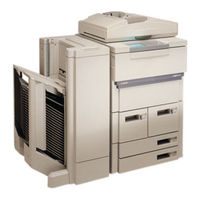
Canon NP6360 Service Manual (794 pages)
Brand:
Canon
| Category:
Printer
| Size: 8.32 MB
Table of Contents
Table of Contents
7
Chapter 1 General Description
21
Features
21
Specifications
22
Copier
22
II. Specifications
22
Mechanisms
22
Type
22
Performance
23
Others
26
Paper Deck-A1
29
Names of Parts
30
External View
30
III. Names of Parts
30
Copier
32
Cross Section
32
Operating the Machine
33
Control Panel
33
Extended Modes
34
Types of User Modes
35
User Mode
35
Points to Note (by the User)
39
Routine Maintenance by the User
39
Image Formation
40
Outline
40
Chapter 2 Basic Operation
43
Basic Operation
43
Basic Mechanisms
45
Functional Construction
45
Outline of the Electrical Circuitry
46
Basic Sequence of Operations
48
Basic Sequence of Operations at Power-On
48
Basic Sequence of Operations
50
Basic Sequence of Operations in Page Separation Mode
52
Main Motor (M1) Control Circuitry
54
Outline
54
Inputs to the DC Controller
56
Outputs from the DC Controller
64
Inputs to and Outputs from Accessories (1/1)
75
Chapter 3 Exposure System
77
Outline of Operation
79
Varying the Reproduction Ratio
79
Outline of the Movement
80
Lens Drive System
80
Movement of the Lens
80
Lens Motor Control Circuit
81
Moving the Lens
81
Moving the Lens
82
Scanner Drive System
84
Scanner Movement
84
Outline of Movement
84
Relationship between the Scanner Sensors and the Signals
85
Controlling the Scanner Motor Brake
86
Outline
86
Movement of the Scanner in Page Separation Mode
88
Movement of the Scanner with the RDF in Use (A4, 2 Originals, 1 Copy)
90
Movement of the Scanner with the RDF in Use (A4, 2 Copies)
92
Scanner Motor (M3) Control Circuit
95
Others
98
Original Size Detection
98
Outline of Detection
98
Operation
99
Size of Originals
100
Disassembly and Assembly
101
Scanner Drive Assembly
102
Motor
102
Removing the Scanner Drive
102
Glass
104
Orienting the Heat Absorbing
104
Routing the Scanner Drive Cable
104
Removing the Scanner Drive Cable
105
Adjusting the Tension of the Scanner Drive Cable
107
Positioning the Mirror
107
Positioning the Scanner Locking Solenoid (SL1)
108
Lens Drive Assembly
109
Removing the Lens y Direction Drive Motor
109
Installing the Light-Blocking Belt Mount
112
Removing the Lens X Direction Drive Motor
112
Attaching the Lens X Direction Drive Belt
113
Routing the Light-Blocking Belt
113
Chapter 4 Image Formation System
115
Processes
117
Controlling the Drum Surface Potential
117
Outline
117
Control Method
118
Potential Measurement Circuit
120
Controlling the Intensity of the Scanning Lamp
122
Outline
122
Auto Exposure Control
123
Operation
123
Making Checks
126
Controlling the Primary/Transfer Corona Current
127
Controlling the Primary Corona Current
127
Outline
127
Controlling the Transfer Corona Current
129
Controlling the Separation/Pre-Transfer Corona Current
131
Outline
131
Turning on and off the Separation/Pre-Transfer Corona Current
132
Pre-Transfer Corona Current (DC Component)
133
Separation Corona Current
133
Controlling the DC Component of the Separation/Pre-Transfer Corona Current
134
Controlling the Blanking Exposure Lamp (LED)
135
Controlling the Activation in Reduce Mode
135
Outline
135
Controlling the Activation in Direct Mode
135
Controlling the Activation in Sheet Frame Erase Mode
135
Lamp (LED)
135
Controlling the Activation in Original Frame Erase Mode
136
Controlling the Activation in Book Frame Erase Mode
136
Controlling the Activation in Hole Image Erase Mode
137
Controlling the Activation in AE Mode
137
Drum Heater Circuit
138
Outline
138
Idle Rotation of the Photosensitive Drum and the Developing Cylinder
140
Cleaning the Primary Charging Wire
141
Outline
141
Automatic Cleaning Mechanism
141
Pre-Transfer/Transfer/Separation Charging Wire Automatic Cleaning Mechanism
142
Drum Cleaning Assembly/Developing Assembly
144
Outline
144
Detecting the Level of Toner and Controlling the Supply Operation
146
Controlling the Developing Bias/Roller Electrode
148
Outline
148
Control Timing
148
Developing Bias Control Circuit
151
Roller Electrode Bias Control Circuit
152
Detecting the Waste Toner Feeding Screw (Locking)
154
Disassembly and Assembly
155
Scanning Lamp Assembly
156
Removing the Scanning Lamp
156
Removing the Thermal Fuse
157
Standard White Plate
157
Pre-Exposure Lamp Unit
158
Removing the Pre-Exposure Lamp Unit
158
Blanking Exposure Lamp Assembly
159
Removing the Blanking Exposure Lamp Assembly
159
Photosensitive Drum
160
Removing the Drum Unit
160
Installing the Photosensitive Drum
162
Replacing the Drum Heater
162
Potential Sensor Assembly
162
Removing the Potential Sensor Assembly
162
Primary Charging Assembly
163
Removing the Primary Charging Assembly
163
Pre-Transfer Charging Assembly
163
Removing the Pre-Transfer Charging Assembly
163
Transfer/Separation Charging Assembly
164
Assembly
164
Removing the Transfer/Separation Charging Assembly
164
Separation Charging Assembly
165
Charging Wire
167
Stringing the Charging Wires
167
The Primary Charging Assembly
167
Stringing the Grid Wire of the Primary Charging Assembly
169
Cleaning the Primary Charging Assembly Anti-Stray Sheet
172
Developing Assembly
173
Removing the Blade Unit
174
Cylinder and the Magnetic Seal
175
Installing the Blade
175
Hopper Assembly
178
Removing the Hopper Assembly from the Copier
178
Drum Cleaner
178
Construction
178
Removing the Cleaning Blade
178
Installing the Cleaning Blade
179
Installing the Side Seal
180
Separation Claw/Separation Claw Drive Assembly
182
Removing from the Drum Unit
182
Waste Toner Feeding Assembly
182
N. Separation Claw/Separation
182
Chapter 5 Pick-Up/Feeding System
185
Pick-Up/Feeding System
185
Outline
187
Pick-Up/Feeding System
187
Cassette Pick-Up
190
II. Cassette Pick-Up
190
Pick-Up Operation
190
Outline
191
Sequence of Pick-Up Operations
191
Cassette Lifter Operation
192
Identifying the Size of Copy Paper in the Cassette (Cassette4 Only)
194
Identifying the Size of Copy Paper
194
Identifying the Size of Copy Paper in the Cassette (Cassette 4 Only)
194
Outline
194
Markings on the Width Guide Rail
196
Paper Size
197
Registering Paper Width Basic Value
198
Front Paper Deck Assembly
199
Outline
199
Pick-Up Operation
200
Sequence of Pick-Up Operations
201
Lifter Operation
202
Operation
202
Deck Limit Detection
204
Detecting the Presence/Absence of Paper in the Deck
205
Detecting the Presence
205
Detecting the Size of the Deck
205
High-Speed Pick-Up
205
Multifeeder
206
Pick-Up Operation
206
Identifying the Size of Paper in the Multifeeder
207
Sequence of Pick-Up Operations (Multifeeder)
208
Controlling the Registration Clutch
209
Making Two-Sided/Overlay Copies
210
Making Two-Sided/Overlay Copies (1St Side)
210
Sequence of Operations (Two-Sided/Overlay Copies; 1St Side)
211
Making Two-Sided Copies (2Nd Side)
212
Sequence of Operations (Two-Sided Copying; 2Nd Side)
213
Making Overlay Copies (2Nd Side)
214
Outline
214
Outline of Operation
215
Sequence of Operations (Overlay Copying; 2Nd Side)
217
Reversal Delivery
218
Sequence of Reversal Delivery Operations
219
Switching the Paper Size for Two-Sided/Overlay/Reversal Delivery Copies
220
Movement of the Paper Size Guide
220
Movement of the Paper Jogging Plate and the Trailing Edge Guide Plate
221
Detecting the Presence/Absence of Copy Paper
222
Re-Pick up from the Holding Tray
223
Outline
224
Skipping Operation
224
Outline of Operations
225
Skipping Operation (Odd Number of Originals)
227
Skipping Operation (Odd Number of Originals)
228
Reversal Delivery
231
Detecting Jams
232
Outline
232
Registration Roller Delay Jam
235
Registration Roller Stationary Jam
235
Pick-Up Vertical Path Feeding 0/1 Delay Jam
236
Pick-Up Vertical Path Feeding 0/1 Stationary Jam
236
Pick-Up Vertical Path Feeding 2 through 4 Delay Jam
237
Pick-Up Vertical Path Feeding 2 through 4 Stationary Jam
237
Fixing Assembly Outlet Delay Jam
238
Fixing Assembly Outlet Stationary Jam
238
External Delivery Delay Jam
239
External Delivery Stationary Jam
239
Internal Delivery Delay Jam
240
Internal Delivery Stationary Jam
240
Holding Tray Inlet Delay Jam
241
Holding Tray Inlet Stationary Jam
241
Holding Tray Re-Pick up Delay Jam
242
Holding Tray Registration Delay Jam
242
Holding Tray Feeding 1/2 Delay Jam
243
Holding Tray Registration Stationary Jam
243
Holding Tray Feeding 1/2 Stationary Jam
244
Left Deck Pick-Up Delay Jam
244
Fixing Separation Claw Assembly Stationary Jam
245
Left Deck Pick-Up Stationary Jam
245
Disassembly and Assembly
246
Multifeeder Assembly
247
Removing the Multifeeder Assembly
247
Removing the Pick-Up Roller
247
Installing the Pick-Up Roller
248
Removing the Separation Roller
248
Removing the Feeding Roller
250
Removing the Multifeeder Paper Sensor
250
Attaching the Side Guide Timing Belt in the Multifeeder Assembly
252
Adjusting the Pressure of the Pick-Up/Feeding Roller of the Multifeeder
253
Installing the Feeding Roller of
253
The Multifeeder
253
Multifeeder
254
Position of the Pick-Up Roller
254
Front Paper Deck Assembly
255
Assembly from the Copier
255
Removing the Paper Deck
255
Removing the Lifter Cable
256
Changing the Deck Paper Size
260
Adjusting the Deck Registration
262
Right Deck Pick-Up Assembly (Cassette Holder)
263
Removing the Pick-Up Assembly from the Copier
263
Removing the Pick-Up Roller
263
Removing the Feeding Roller
265
Removing the Separation Roller
265
Adjusting the Pressure of the Separation Roller
266
Orientation of the Separation Roller
267
Orientation of the Feeding Roller of the Cassette/Deck Pick-Up Assembly
268
Positioning the Pick-Up Roller Releasing Solenoid of the Deck
268
Positioning the Pick-Up Roller
269
Releasing Solenoid of the Cassette
269
Adjusting the Registration for the Cassette
269
Left Deck Pick-Up Assembly
270
Removing the Pick-Up
270
Assembly from the Copier
270
Removing the Pick-Up Roller
270
Removing the Feeding Roller
272
Removing the Separation Roller
272
Orientation of the Feeding Roller Assembly of the Left Deck Pick-Up Assembly
273
Pick-Up Vertical Path Roller Assembly
273
Removing the Pick-Up Vertical
273
Path Roller Assembly
273
Registration Feeding Assembly
274
Construction
274
Removing the Registration
274
Feeding Assembly
274
Removing the Registration Roller (Upper Rubber Roller)
275
Feeding Assembly
276
Construction
276
Removing the Fixing/Feeding Unit
276
Removing the Feeding Belt
277
Holding Tray Assembly
280
Construction
280
Re-Pick up Assembly
280
Removing the Holding Tray
281
Removing the Holding Tray Re-Pick up Assembly
281
Registration Paper Sensor
282
Removing the Re-Pick up Roller
283
Removing the Holding Tray Driver PCB
283
Removing the Holding Tray y Motor
284
Removing the y Motor Home
286
Position Sensor
286
Removing the Holding Tray Inlet Assembly
286
Removing the Feeding Roller/Separation Belt Assembly
288
Removing the Feeding Roller
289
Removing the Separation Belt Assembly
289
Adjusting the Pressure of the Separation Roller of the Holding Tray
290
Positioning the Holding Tray Paper Deflecting Plate Drive Solenoid
290
Removing the Side Guide Plate Assembly
291
Removing the Holding Tray X Motor
291
Removing the Holding Tray Re-Circulating Motor
291
Assembly
291
Paper Jogging Guide Plate
291
Assembly
292
Removing the Holding Tray Paper Jogging Solenoid
292
Assembly Side Guide Plate Assembly
293
Paper Jogging Guide Plate Assembly
293
Attaching the Timing Belt of
294
The Holding Tray Assembly Paper Jogging Guide Plate
294
Positioning the Holding Tray
294
Holding Tray Feeding Assembly
295
Removing the Holding Tray Feeding Assembly from the Copier
295
Removing the Sensor from the Holding Tray Feeding
296
Chapter 6 Fixing System
297
Outline of Operations
299
Outline
299
Fixing Drive Assembly
301
Controlling the Fixing Temperature
303
Reciprocating Mechanism for the Main Thermistor (TH1)
308
Reciprocating Mechanism for the Upper Separation Claw
309
SSR Error Detection Circuit for the Fixing Heater
310
Locking Operation (Fixing/Feeding Unit)
312
Error Detection Circuit
313
Outline
313
Scanning Lamp Error Activation Detection Circuit
313
Fixing Heater Error Activation Detection Circuit
314
Motor Error Rotation Detection Circuit
315
Disassembly and Assembly
316
Fixing Assembly
317
Construction
317
Locking Mechanism
317
Removing the Fixing Cleaning Belt
317
Installing the Fixing Cleaning Belt
319
Removing the Upper Fixing Unit
320
Removing the Fixing Heater
322
Installing the Fixing Heater
323
Removing the Fixing Upper Roller
323
Installing the Upper Fixing Roller
325
Removing the Thermal Switch
325
Removing the Lower Separation Claw Assembly
327
Removing the Lower Roller
327
Adjusting the Nip (Tightening the Pressure Adjusting Nut)
328
Removing the Upper Separation Claw
328
Adjusting the Fixing Clutch
329
Delivery Assembly
331
Construction
331
Guide (Fixing/Delivery Assembly)
331
Removing the External Delivery Roller
332
Outlet Paper Sensor Assembly
333
Paper Sensor and the Internal Delivery Paper Sensor
333
Removing the Internal Delivery Assembly Roller
334
Chapter 7 Externals/Auxiliary Mechanisms
335
Control Panel
337
Outline
337
Operation
337
Data Communication
337
LCD Processing
338
Automatic Control of LCD Contrast
340
Touch Switch Inputs
341
Fans
342
II. Fans
342
Power Supply
345
III. Power Supply
345
Outline of Power Supply
345
Power Supply Circuit
346
Date/Time Display Power Supply
348
Disassembly and Assembly
349
External Covers
350
Removing the Front Door
351
Removing the Inside Upper Cover
352
Removing the Fixing/Feeding Unit
352
Removing the Rear Cover
353
Sliding out the Hopper Assembly
353
Removing the Process Unit
354
Installing the Process Unit
356
Control Panel
357
Removing the Control Panel from the Copier
357
Removing the Control Panel PCB
359
Removing the Touch Panel
360
Controller (CPU) PCB
361
Removing the Control Panel
361
Door Switch Assembly
362
Removing the Front Door
362
Removing the Multifeeder Door Switch Assembly
362
Switch Assembly
362
Installing the Drum Heater Switch
363
Fan Unit
364
Removing the Exhaust Fan
364
Removing the Scanner Cooling Fan
364
Exhaust Fan
365
Removing the Developing Fan
365
Removing the Fixing Heat
365
Removing the Cleaner Fan
366
Cooling Fan
367
Removing the Feeding Fan
367
Removing the Scanner Motor
367
Removing the Counter Assembly
368
Main Motor Assembly
368
Removing the Main Motor
368
Fixing/Waste Toner Drive Assembly
369
Construction
369
Removing the Fixing/Waste Toner Drive Assembly
369
Removing the Waste Toner Bottle
369
Main Drive Assembly (Drum/Developing)
371
Main Drive Assembly
371
Construction
371
Vertical Path Drive Assembly
372
Construction
372
Removing
372
Pick-Up Drive Assembly
374
Construction
374
Removing
374
Duplexing Drive (1) Assembly
375
Construction
375
Removing
375
Lifter Drive Assembly
376
Construction
376
Removing
376
Construction
377
Cassette Pick-Up Drive Assembly
377
Attaching the Drive Belt
379
DC Controller PCB
380
DC Power Supply Assembly
381
High-Voltage Transformer Assembly
382
Q. High-Voltage Transformer
382
Power Supply Inlet Assembly
383
Chapter 8 Paper Deck-A1
385
Side Paper Deck
387
Inputs to and Outputs from the Side Deck Driver
387
Outputs from the Side Deck Driver
389
Outline
390
Pick-Up
390
Pick-Up Operation
390
Sequence of Operations (Deck Pick-Up)
392
Detection of Paper for the Deck
393
Changing the Paper Size for the Deck
393
Detecting the Presence/Absence of Paper
393
Deck Lifter
394
(Compartment)
397
Opening/Closing the Deck (Compartment)
397
Sequence of Operations (Deck Opening/Closing)
398
Controlling the Deck Motor
399
Controlling the Deck Main Motor (M101)
399
Controlling the Deck Lifter Motor (M102)
401
Outline
403
Detecting Jams
403
Deck Pick-Up/Vertical Path Delay Jam
404
Deck Pick-Up/Vertical Path Stationary Jam
404
When Copy Paper Is Present at any of the Sensors at Power-On, End of Wait-Up, or During Standby
404
Disassembly and Assembly
405
External Covers
406
Removing the
406
Removing the Right Cover
409
Removing the Vertical Path Cover (Rear)
409
Removing the Upper Cover
410
Paper Deck
412
Removing the Deck from the Copier
412
Removing the Compartment
414
Changing the Deck Paper Size
416
Adjusting the Deck Registration
417
Positioning the Roll
417
Drive System
418
Clutch (CL102)
418
Removing the Deck Vertical Path Clutch (CL101)
418
Removing the Deck Main Motor (M101)
419
Removing the Deck Lifter Motor (M102)
420
Routing the Lifter Cable
425
Feeding System
426
Removing the Deck Pick-Up Unit
426
Orientation of the Deck Pick-Up Roller
427
Orientation of the Deck Feeding Roller
428
Removing the Deck Feeding Roller
428
Removing the Deck Separation Roller
429
Adjusting the Deck Separation Roller Pressure
430
Removing the Deck Pick-Up Roller
430
Electrical System
431
Removing the OPEN Switch PCB
431
Removing the Side Deck Driver PCB
431
Chapter 9 Installation
433
Selecting the Site
435
Unpacking and Installing
438
Unpacking
439
Installing the Scanner
441
Installing the Fixing Assembly
442
Charging Assemblies
444
Installing the AP Kit and the Charging Assemblies
444
Installing the Copy Tray
450
Replacing the Delivery Roller Leaf Spring
450
Checking the Developing Assembly
451
Installing the Pick-Up Assembly
453
Supplying Toner
455
Connecting the RDF Connector
459
Image/Operation Checks and User Mode
460
Image/Operation Checks and User Mode
464
Relocating the Machine
465
Installing the Control Card V
466
Installing the Copy Data Controller-A1
474
Setting the Board
474
Installation Procedure
476
Installing to the Copier
478
Checking the Operation
480
Installing the Remote Diagnostic Device II
490
Installation to the Copier
490
Chapter 10 Maintenance and Inspection
501
Periodically Replaced III. Parts
503
Consumables and Durables.10-2
504
A. Copier
504
Paper Deck-A1
505
Scheduled Servicing Table
506
Scheduled Servicing Chart
508
A. Copier
508
B. Paper Deck-A1
510
Chapter 11 Troubleshooting
511
Maintenance and Inspection.11-3
515
Image Adjustment Basic Procedure
515
Points to Note for Scheduled Servicing
516
Standards/Adjustments
517
Adjusting the Image Leading Edge Margin
517
Adjusting the Image Leading Edge Non-Image Width (Registration)
517
II. Standards/Adjustments
517
Image Adjustment
517
Adjusting the Left/Right Registration (Left/Right Front Deck Paper Deck, Cassette)
518
Adjusting the Left/Right Registration (Paper Deck-A1)
519
Adjusting the Left/Right Margin
520
Adjusting the Left/Right Registration (Holding Tray Position; 2Nd Side of Two- Sided/Overlay Copies)
520
Executing AE Automatic Adjustment
521
Adjusting the AE Slope
522
Adjusting the Distance between the Side Guide Plates of the Holding Tray Assembly
522
Exposure System
523
Routing the Scanner Drive Cable
523
Adjusting the Tension of the Scanning Lamp Cable
524
Orientation of the Heat Absorbing Glass
524
Adjusting the Position of the Mirror
525
Cleaning the Mirror (No. 5 Mirror)
526
Routing the Light-Blocking Belt
526
Adjusting the Position of the Scanner Locking Solenoid
527
Routing the Lens X Direction Drive Belt
527
Grid Wire of the Primary Charging Assembly
528
Image Formation System
528
Adjusting the Height of the Charging Wire
530
Adjusting the Position of the Blanking Exposure Lamp
531
Adjusting the Position of the Cleaning Assembly Side Seal
532
Position of the Roller Electrode
532
Cleaning the Cleaner Side Scraper
533
Orientation of the Cassette/Front Paper Deck Pick-Up Roller
535
Pick-Up/Feeding System
535
Orientation of the Cassette/Front Paper Deck Separation Roller
536
Orientation of the Feeding Roller (Cassette/Front Paper Deck)
536
Orientation of the Multifeeder Pick-Up Roller
537
Orientation of the Paper Deck-A1 Feeding Roller
538
Rotation of the Multifeeder Feeding Roller
538
Adjusting the Separation Roller Pressure of the Cassette/Front Paper Deck
539
Adjusting the Separation Roller Pressure of the Holding Tray
540
Pick-Up/Feeding Roller of the Multifeeder
540
Adjusting the Position of the
541
Adjusting the Position of the Pick-Up Roller Releasing Solenoid (Front Paper Deck)
542
Adjusting the Position of the Pick-Up Roller Releasing Solenoid (Paper Deck-A1)
542
Adjusting the Position of the Pick-Up Roller Releasing Solenoid (Multifeeder)
543
Adjusting the Position of the Solenoid (Delivery Paper Deflecting Plate Solenoid)
544
Routing the Timing Belt of the Side Guide (Multifeeder Assembly)
544
Adjusting the Position of the Holding Tray Assembly Side Guide Plate
545
Adjusting the Position of the Holding Tray Paper Deflecting Plate Drive Solenoid
545
Holding Tray Paper Jogging Plate
546
The Holding Tray Paper Jogging Guide Plate
546
Adjusting the Position of the Holding Tray Paper Jogging Plate
547
Adjusting the Position of the Holding Tray Paper Jogging Plate Solenoid
547
Drive Belt
547
Fixing System
549
Adjusting the Position of the Fixing Assembly Inlet Guide
549
Points to Note When Installing the Fixing Heater
549
Adjusting the Lower Roller Pressure (Nip)
551
Adjusting the Fixing Clutch
552
Electrical System
553
Checking the Surface Potential Control System
553
When Replacing the DC Controller PCB
553
Checking the Potential System
557
Potential Control System Conversion Table
559
Checking the
564
Checking the Environment Sensor
564
Checking the Photointerrupters
565
Registering the Paper Width Basic Value ( 4 ; Cassette/ Multifeeder)
573
Image Faults
574
Initial Checks
574
Checking the Originals
574
Checking the Site Environment
574
Checking the Charging Assemblies
575
Checking the Copyboard Cover, Copyboard Glass, and Standard White Plate
575
Checking the Developing Assembly
575
Checking the Paper
575
Checking the Periodically Replaced Parts
575
Others
575
Sample Image Faults
577
Troubleshooting Image Faults
579
The Copy Is too Light (Halftone Only)
579
The Copy Is too Light (Entire Face)
580
The Copy Is too Light (Including Solid Black)
580
The Copy Has an Uneven Density (Darker at Front)
582
The Copy Has an Uneven Density (Lighter at Front)
582
The Copy Is Foggy. (Overall)
583
The Copy Has Black Lines (Vertical, Fuzzy, Thick)
584
The Copy Has Vertical Fogging
584
The Copy Has Black Lines (Vertical, Fine)
585
The Copy Has White Lines (Vertical)
586
The Copy Has White Spots (Vertical)
586
The Copy Has White Spots (Horizontal)
588
The Copy Has a Soiled Back
589
The Copy Has Fixing Faults
590
16., 17. the Copy Has Displaced Leading Edge Registration
591
The Copy Is Blurred and Fuzzy
592
The Copy Has Horizontal Fogging
593
The Copy Has Poor Sharpness
593
The Copy Is Blank
594
The Copy Is Solid Black
594
A. Troubleshooting Malfunctions
595
E001
596
Troubleshooting Malfunctions
595
E000
595
E002
597
E003
597
E004
597
E005
598
E006
598
E010
598
E013
599
E015
600
E020
601
E030 (the Total Copy Counter Fails to Turn On.)
602
E031 (the Option Counter Has an Open Circuit.)
602
E043 (Paper Deck-A1)
603
E050
604
E051
604
E202 (the Keys on the Control Panel Are Locked.)
605
E203
605
E204 (the Keys on the Control Panel Are Locked.)
605
E210 (Fault in Lens X Direction Drive System)
606
E212 (Fault in Lens y Direction Drive System)
606
E213
606
E214
606
E240
607
E243
607
E710/E711
607
E712
607
E713
608
E800
608
E802
608
AC Power Is Absent
609
DC Power Supply Is Absent
610
Pick-Up Fails. (Deck Pick-Up; Front Paper Deck + Cassette)
611
The Deck Lifter Fails to Move up
612
Pick-Up Fails. (Cassette Pick-Up)
613
The Lifter Fails to Move up
615
(Cassette)
615
Pick-Up Fails. (Multifeeder)
616
The Registration Roller Fails to Rotate
617
The Vertical Path Roller Fails to Rotate
617
The Scanner Fails to Move Forward
618
The Scanner Fails to Move in Reverse
618
The Blanking Exposure Lamp Fails to Turn on
619
The Pre-Exposure Lamp Fails to Turn on
619
The Scanning Lamp Fails to Turn on
620
The Hopper Motor (M10) Fails to Operate
621
The Drum Heater Fails to Operate
622
The Hopper Motor (M11) Fails to Operate
622
The Lens Fails to Move
623
The Add Toner Indicator Fails to Turn off
624
The Add Toner Indicator Fails to Turn on
624
Jams Occur at the Fixing Assembly Inlet
625
The Add Paper Message Fails to Turn off
625
The Set Control Card Message Fails to Turn off
625
The Fixing Heater Fails to Operate
626
Pick-Up Fails. (Paper Deck-A1)
627
The Deck Lifter Fails to Move Up. (Paper Deck-A1)
628
Troubleshooting Feeding Problems
629
Copy Paper Jams
629
Pick-Up Assembly
630
Separation/Feeding Assembly
631
Fixing/Delivery Assembly
632
Fixing/Delivery Assembly (Reversed Delivery)
632
Cleaning Assembly
633
Holding Tray Assembly (Two-Sided/Overlay Copying, 1St Side)
633
Holding Tray Assembly (Re-Pick Up)
634
Holding Tray Assembly (Overlay, Re-Pick Up)
635
Holding Tray Feeding Assembly
635
Double Feeding
636
Feeding Faults
636
Wrinkles
636
Arrangement and Functions of Electrical Parts
637
Sensors
638
Motors and Fans
646
Clutches
648
Lamps, Heaters, and Photosensors
650
Pcbs
652
Paper Deck-A1
654
Sensors and Switches
654
Motors, Clutches, Solenoids, and Pcbs
656
Variable Resistors (VR), Light-Emitting Diodes (LED), and Check Pins by PCB
658
DC Controller PCB
658
AC Driver PCB
661
DC Power Supply PCB
661
Control CPU PCB
662
Holding Tray Driver PCB
663
Potential Measurement PCB
664
Hvt1 Pcb
665
Hvt2 Pcb
666
Inverter PCB
666
Counter PCB
667
Lamp Regulator PCB
667
Side Deck Driver (Paper Deck-A1)
668
A. Outline
669
VII. Service Mode
669
C. Using Adjustment Mode and Options Mode
670
Using Service Mode
670
Display Mode
672
I/O Display Mode ( 2 )
689
Adjustment Mode
725
Function Mode
743
Options Mode
754
Counter Mode
766
Self Diagnosis
772
A. Copier
772
B. Rdf-D
777
Rdf-D1
777
C. Sorter
779
Appendix
781
Paper Deck-A1 General Circuit Diagram
789
Special Tools
791
Advertisement
Advertisement
Related Products
Canon NP6317
Canon NP6320
Canon NP6560
Canon NP6260
Canon NP6085
Canon NP6218
Canon NP6612
Canon NP6512
Canon NP6045
Canon NP6621
Canon Categories
Printer
Digital Camera
All in One Printer
Camcorder
Scanner
More Canon Manuals
Login
Sign In
OR
Sign in with Facebook
Sign in with Google
Upload manual
Upload from disk
Upload from URL