Sign In
Upload
Manuals
Brands
Canon Manuals
All in One Printer
imageRunner iR4570
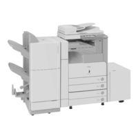
Canon imageRunner iR4570 Manuals
Manuals and User Guides for Canon imageRunner iR4570. We have
3
Canon imageRunner iR4570 manuals available for free PDF download: Service Manual
Canon imageRunner iR4570 Service Manual (183 pages)
Brand:
Canon
| Category:
Copier
| Size: 2.77 MB
Table of Contents
Table of Contents
5
Chapter 1 Specifications
9
Product Specifications
11
Chapter 2 Functions
14
Basic Construction
16
Overview
16
G3 Fax Controll
17
Chapter 3 Parts Replacement Procedure
18
Removing from the Host Machine
20
FAX Unit
20
Removing of the FAX Unit
20
Chapter 4 Service Mode
22
Outline
27
Service Mode Composition
27
Using Service Mode
27
Menu Items
30
Setting of Bit Switch (SSSW)
33
Outline
33
Bit Switch Composition
33
SSSW-SW01: Error/Copy Management
34
Detailed Discussions of Bit 0
34
Detailed Discussions of Bit 1
34
Functional Construction
34
SSSW-SW03: Setting of Echo Measures
35
Detailed Discussions of Bit 1
35
Functional Construction
35
Detailed Discussions of Bits 4, 5, and 6
36
Detailed Discussions of Bit 7
37
SSSW-SW04: Setting of Communication Trouble Measures
37
Functional Construction
37
Detailed Discussions of Bit 2
38
Detailed Discussions of Bit 3
38
Detailed Discussions of Bit 4
38
SSSW-SW05: Setting of Standard Functions (DIS Signal)
39
Functional Construction
39
Detailed Discussions of Bit 1
39
Detailed Discussions of Bit 2
39
Detailed Discussions of Bit 3
39
Detailed Discussions of Bit 4
40
SSSW-SW12: Setting of
40
Functional Construction
40
SSSW-SW14: Setting of Inch/Millimeter-Base Resolution
42
Functional Construction
42
Detailed Discussions of Bit 2
43
Detailed Discussions of Bit 4
43
Sssw-Sw24
43
Functional Construction
43
Functional Construction
44
Detailed Discussions of Bit 0
44
Detailed Discussions of Bit 1
44
Detailed Discussions of Bit 2
44
Detailed Discussions of Bit 3
44
Detailed Discussions of Bit 7
44
SSSW-SW25: Setting of Report Indication Functions
44
Detailed Discussions of Bit 4
44
SSSW-SW26: Setting of Transmission Functions
45
Functional Construction
45
Detailed Discussions of Bit 2
45
Detailed Discussions of Bit 7
46
SSSW-SW28: Procedure Setting for V.8/V.34
46
Functional Construction
46
Detailed Discussions of Bit 2
47
Detailed Discussions of Bit 7
47
Detailed Discussions of Bit 0
47
Detailed Discussions of Bit 1
47
Detailed Discussions of Bit 3
47
Detailed Discussions of Bit 4
47
Detailed Discussions of Bit 5
47
Setting of Menu Switch (MENU)
48
Menu Switch Composition
48
005: NL Equalizer
48
006: Telephone Line Monitor
49
007: ATT Transmission Level
49
008: V.34 Modulation Speed Upper Limit
50
009: V.34 Data Speed Upper Limit
50
Setting of Numeric Parameter (NUMERIC Param.)
51
Numerical Parameter Composition
51
002: RTN Transmission Condition (1)><003: RTN Transmission Condition
52
002: RTN Transmission Condition (1)><003: RTN
52
005: NCC Pause Length (Pre-ID Code)
53
006: NCC Pause Length (Post-ID Code)
53
007: Pre-Pause Length at Time of Ring
53
009: Number of Comparison Digits of Source Telephone Number and Target Telephone Number
53
010: Line Connection Identification Length
53
011: T.30 T1 Timer (for Reception)
53
009: Number of Comparison Digits of Source
53
013: T.30 EOL Timer
54
027: V.21 Low-Speed Flag Preamble Identification Length
54
027: V.21 Low-Speed Flag Preamble Identification
54
Setting of Destination (TYPE)
55
Overview
55
Setting of Printer Functions (PRINTER)
56
Setting of Bit Switch (SSSW)
56
Detailed Discussions of Bits 0 and 1
56
Functional Construction
56
SSSW-SW05: Setting of Reduction/Cassette Selection
56
Detailed Discussions of Bit 7
57
Functional Construction
57
SSSW-SW06: Reduction Setting
57
Setting of Numeric Parameter (NUMERIC Param.)
58
Detailed Discussions of Bit 5
58
Numerical Parameter Composition
58
001: Printing Upon Reception of Extra-Length Image
59
004: Leading Edge Margin
59
005: Trailing Edge Margin
59
Initialization of Set Value (CLEAR)
60
Overview
60
Default Settings
61
Test Mode (TEST)
72
Outline
72
Test Mode Construction
72
MODEM Test
73
Relay Test (RELAY-1)
73
Frequency Test (FREQ)
74
G3 Signal Transmission Test (G3 Tx)
75
DTMF Transmission Test
77
G3 Signal Transmission Test (V34G3Tx)
77
Function Test
79
4800-Bps Signal Transmission Test
79
Service Report (REPORT)
80
System Data List
80
System Dump List
81
Error Transmission Report
84
Chapter 5 Error Code
85
Overview
87
Guide to Error Code
87
User Error Code
90
Service Error Code
91
Chapter 1 Specifications
105
Chapter 2 Functions
110
Basic Construction
112
Overview
112
G3 Fax Controll
113
Chapter 3 Parts Replacement Procedure
114
FAX Unit
116
Removing from the Host Machine
116
Removing of the FAX Unit
116
Chapter 4 Service Mode
118
Outline
123
Service Mode Composition
123
Using Service Mode
123
Bit Switch Composition
129
Outline
129
Setting of Bit Switch (SSSW)
129
Detailed Discussions of Bit 0
130
Detailed Discussions of Bit 1
130
Functional Construction
130
SSSW-SW01: Error/Copy Management
130
Functional Construction
131
Detailed Discussions of Bit 1
133
Functional Construction
133
SSSW-SW04: Setting of Communication Trouble Measures
133
Detailed Discussions of Bit 2
134
Detailed Discussions of Bit 3
134
Detailed Discussions of Bit 4
134
Detailed Discussions of Bit 1
135
Detailed Discussions of Bit 2
135
Detailed Discussions of Bit 3
135
Functional Construction
135
SSSW-SW05: Setting of Standard Functions (DIS Signal)
135
Functional Construction
136
Functional Construction
138
SSSW-SW14: Setting of Inch/Millimeter-Base Resolution
138
Detailed Discussions of Bit 2
139
Detailed Discussions of Bit 4
139
Functional Construction
139
Sssw-Sw24
139
Detailed Discussions of Bit 0
140
Detailed Discussions of Bit 1
140
Detailed Discussions of Bit 2
140
Detailed Discussions of Bit 3
140
Detailed Discussions of Bit 7
140
Functional Construction
140
SSSW-SW25: Setting of Report Indication Functions
140
Detailed Discussions of Bit 0
141
Functional Construction
141
SSSW-SW26: Setting of Transmission Functions
141
Detailed Discussions of Bit 2
142
Detailed Discussions of Bit 7
142
Functional Construction
142
Detailed Discussions of Bit 0
143
Detailed Discussions of Bit 1
143
Detailed Discussions of Bit 2
143
Detailed Discussions of Bit 3
143
Detailed Discussions of Bit 4
143
Detailed Discussions of Bit 5
143
005: NL Equalizer
144
Menu Switch Composition
144
Setting of Menu Switch (MENU)
144
006: Telephone Line Monitor
145
007: ATT Transmission Level
145
008: V.34 Modulation Speed Upper Limit
146
009: V.34 Data Speed Upper Limit
146
002: RTN Transmission Condition (1)><003: RTN Transmission Condition
148
005: NCC Pause Length (Pre-ID Code)
149
006: NCC Pause Length (Post-ID Code)
149
007: Pre-Pause Length at Time of Ring
149
009: Number of Comparison Digits of Source Telephone Number and Target Telephone Number
149
010: Line Connection Identification Length
149
011: T.30 T1 Timer (for Reception)
149
013: T.30 EOL Timer
150
027: V.21 Low-Speed Flag Preamble Identification Length
150
Overview
151
Setting of Destination (TYPE)
151
Setting of Bit Switch (SSSW)
152
Setting of Printer Functions (PRINTER)
152
SSSW-SW05: Setting of Reduction/Cassette Selection
152
SSSW-SW06: Reduction Setting
153
Initialization of Set Value (CLEAR)
156
Overview
156
Default Settings
157
Outline
159
Test Mode (TEST)
159
Test Mode Construction
159
MODEM Test
160
Relay Test (RELAY-1)
160
Frequency Test (FREQ)
161
G3 Signal Transmission Test (G3 Tx)
162
DTMF Transmission Test
164
G3 Signal Transmission Test (V34G3Tx)
164
4800-Bps Signal Transmission Test
166
Function Test
166
Service Report (REPORT)
167
System Data List
167
Chapter 5 Error Code
172
Guide to Error Code
174
Overview
174
User Error Code
177
Service Error Code
178
Product Specifications
107
Advertisement
Canon imageRunner iR4570 Service Manual (233 pages)
Brand:
Canon
| Category:
All in One Printer
| Size: 6.76 MB
Table of Contents
Table of Contents
5
Chapter 1 Specifications
11
Chapter 1 Specifications
12
Product Specifications
13
Specifications
13
Names of Parts
18
External View
18
Cross-Sectional View
19
Chapter 2 Functions
20
Chapter 2 Functions
21
Basic Construction
22
Overview
22
Outline of Electric Circuits
23
Basic Operation
24
Feed Drive System
29
Overview
29
Feed Roller Control
30
Offset Roller Control
31
Feed Motor Control
35
Offset Motor Control
36
Staple Operation
37
Functional Configuration
37
Staple Motor Control
39
Stack Tray Operation
40
Overview
40
Stack Ejection
41
Stack Slide Motor Control
43
Stack Tray Shift Motor Control
44
Detecting Jams
45
Overview
45
Power Supply
47
Overview
47
Protection Function
47
Chapter 3
49
Left Cover
55
Removing the Left Cover
55
Upper Cover
55
Removing the Upper Cover
55
PCB Cover
56
Bottom Cover
57
Removing the Bottom Cover
57
Top Harness Cover
57
Removing the Top Harness Cover
57
Tray Guide Top Cover
58
Drive System
60
Drive Unit
62
Removing the PCB Cover
63
Feed Motor
63
Stack Tray Shift Motor
63
Removing the Top Harness Cover
64
Removing the Upper Cover
64
Removing the Bottom Cover
65
Removing the Left Cover
65
Removing the Stapler Cover
68
Offset Motor
71
Removing the PCB Cover
71
Removing the Top Harness Cover
72
Removing the Upper Cover
72
Removing the Offset Motor
73
Stack Slide Motor
73
Document Feeding System
78
Stack Tray Assembly
78
Process Tray Assembly
81
Feed Rollor
85
Removing the PCB Cover
85
Removing the Top Harness Cover
88
Electrical System
88
Stack Tray Paper Surface Sensor
88
Removing the Stack Tray Lower Limit Sensor
92
Process Tray Paper Sensor
92
Removing the PCB Cover
96
Removing the Process Tray Paper Sensor
96
Finisher Controller PCB
96
Front Cover Safety Switch
98
Removing the PCB Cover
98
Inlet Sensor
98
Removing the Top Harness Cover
99
Removing the Upper Cover
99
Removing the Inlet Sensor
100
Stack Slide HP Sensor
101
Stack Slide HP Sensor
104
Chapter 4 Maintenance
118
Maintenance and Inspection
119
Periodically Replaced Parts
119
Durables
119
Periodical Servicing
120
Adjustment
121
Adjustment at Time of Parts Replacement
121
Outline of Electrical Components
122
Variable Resistors (VR), Light-Emitting Diodes
125
Light-Emitting Diodes and Check Pins by PCB
125
Finisher Controller PCB
126
Offset HP Sensor
127
DIP Switch Functions
128
Table of Contents
143
Chapter 1 Specifications
145
Product Specifications
147
Specifications
147
Names of Parts
150
External View
150
Cross Section
151
Basic Construction
154
Functional Construction
154
Feed Drive System
155
Overview
155
Constraction of the Control System
156
Punch Operation
157
Power Supply
162
Power Supply Route
162
Protection Function
162
Chapter 3 Parts Replacement Procedure
163
External Covers
165
Front Cover
165
Removing the
165
Upper Cover
166
Electrical System
171
Photosensor PCB
171
Punch Controller PCB
172
Chapter 4 Maintenance
175
User Maintenance
177
User Maintenance Items
177
Adjustment
178
Adjustment at Time of Parts Replacement
178
Registering the Number of Punch Holes
178
Sensors
179
Motors and Solenoids
180
Pcbs
181
Variable Resistors (VR), Light-Emitting Diodes (LED), and Check Pins by PCB
182
Outline
182
Functions of the DIP Switch
183
Punch Controller PCB
183
Chapter 5 Error Code
186
Overview
188
Outline
188
Service Error Code
189
E590
189
Jam Codes
190
Detecting a Jam
190
Alam Code
191
Punch Waste Case Full
191
Punch Waste Case Overflow
192
Table of Contents
200
Chapter 1 Specifications
202
Specifications
204
Chapter 2 Functions
206
Chapter 3 Parts Replacement Procedure
209
Removing from the Host Machine
211
Shift Tray
211
Turning off the Host Machine
211
Mounting the Optional Tray
216
Electrical System
218
Stack Tray Paper Surface Sensor
218
Removing the Option Tray (Lower) Cover
218
Removing the Paper Sensor
218
Static Charge Eliminator 1
218
Removing the Main Tray Cover
219
Removing the Side Plate L Cover
219
Optional Tray Driver PCB
220
Removing the Option Tray (Lower) Cover
220
Removing the Option Tray Drive PCB
220
Chapter 4 Maintenance
222
Maintenance and Inspection
224
Periodically Replaced Parts
224
Durables
224
Periodical Servicing
225
Outline of Electrical Components
226
Variable Resistors (VR), Light-Emitting Diodes (LED), and Check Pins by PCB
227
Functions of the DIP Switch
227
Canon imageRunner iR4570 Service Manual (108 pages)
Brand:
Canon
| Category:
All in One Printer
| Size: 1.43 MB
Table of Contents
Table of Contents
5
Chapter 1 Specifications
7
Product Composition
9
Product Configuration
9
Specifications
11
Chapter 2 Functions
15
Changed Function
17
Changes from Ir 2220I/Ir2820I/3320I
17
New Function
22
Authentication at TX
22
Encrypted Transmission
27
Authentication at RX
28
Encrypted Reception
33
MAC Address Block Function
36
URL Transmission
36
Setting for Communicate SSL
36
Chapter 3 Installation
37
Installation Procedure
39
Overview of the Installation Procedure
39
Chapter 4 Maintenance
41
Notes When Service
43
Points to Note
43
Troubleshooting
44
Related Error Code
49
E-Mail Transmission Errors
49
I-Fax Transmission Errors
54
I-Fax Reception Errors
59
SMB Reception Errors
63
FTP Transmission Errors
67
NCP Transmission Errors
69
Box Transmission Errors
72
Related Service Mode
74
Related Service Modes List
74
Invalidating the License for Transfer to a Different Device (Category 2)
75
Chapter 1 Specifications
85
Product Components
87
Product Composition
87
Important Note
88
Specifications
89
Limitations
93
User Environment
93
Chapter 2 Functions
94
Chapter 3 Installation
100
Installation Procedure
101
Overview of the Installation Procedure
101
Chapter 4 Maintenance
103
Invalidating the License for Transfer to a Different Device (Category 2)
105
Related Service Mode
105
Encrypted PDF
96
New Function
96
Searchable PDF
96
Document Orientation Auto Detection
97
File Name OCR
98
Advertisement
Advertisement
Related Products
Canon IMAGERUNNER 2020
Canon imageRUNNER 5075
Canon imageRUNNER 2000
Canon IMAGERUNNER 2016
Canon ImageRunner 5050
Canon imageRUNNER 2220 Series
Canon imageRUNNER 1025
Canon ImageRunner 600
Canon imageRunner 2018
Canon imageRUNNER2800
Canon Categories
Printer
Digital Camera
All in One Printer
Camcorder
Scanner
More Canon Manuals
Login
Sign In
OR
Sign in with Facebook
Sign in with Google
Upload manual
Upload from disk
Upload from URL