Sign In
Upload
Manuals
Brands
ABB Manuals
Transmitter
LWT300 series
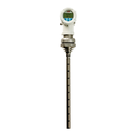
ABB LWT300 series Guided Wave Radar Manuals
Manuals and User Guides for ABB LWT300 series Guided Wave Radar. We have
5
ABB LWT300 series Guided Wave Radar manuals available for free PDF download: User Manual, Quick Start Manual
ABB LWT300 series User Manual (108 pages)
Guided wave radar level transmitter
Brand:
ABB
| Category:
Radar
| Size: 7.01 MB
Table of Contents
Table of Contents
3
1 Safety
5
Definitions
5
Personnel
7
Electrical
7
Grounding
8
Environmental (WEEE)
9
Cybersecurity
9
Modbus Protocol Disclaimer
10
General Deployment Guidelines
10
2 Introduction
11
About this Guide
11
Basics of LWT Level Measurement
11
First Look
13
The Head
13
The Coupler
14
As Shipped
14
Basic Installation Procedure
15
Modbus-Specific Considerations
15
Disclaimers
16
Improper Use
16
Technical Limit Values
16
Operator Liability
16
3 Installing the LWT
17
Safety First
17
Before You Start
17
Environmental Considerations
18
Power Considerations
18
Cable- and Cable Gland Considerations
18
Vessel Considerations
19
Gathering Necessary Tools
20
Accessing the Location
20
Assembling a Segmented Probe
21
Attaching a Probe to the Coupler
23
Installing the LWT Instrument
25
Rotating the Housing
25
Rotating the HMI
26
Installing a Remote Head LWT Instrument
28
Grounding the Instrument
31
Connecting the Instrument
32
Upon Startup
35
4 Introducing the User Interface
37
Introducing the User Interface
37
Introducing LWT User Interfaces
37
Accessing Menus
38
Navigating the Instrument Display
38
5 Configuring the Instrument at Startup
41
6 Configuring the Instrument
43
Configuring the Display
43
Contrast
43
Number of Decimals
43
Configuring Operator Pages
44
Selecting an Operator Page to Display
45
Enabling Operator Page Autoscroll
45
Protecting Access to Instrument Data
46
Setting up Role-Based Passwords
46
Resetting Passwords
46
Disabling Access to the Service Account
47
Preventing Unwanted Deletion of Data
47
Setting Dynamic Variables
49
Setting Variables
49
Setting Variable Units
49
Configuring the Sensor
50
Selecting the Application Category
50
Setting the Dielectric Constant of Upper Media
51
Configuring Gas Phase Compensation
51
Resetting Echo Tracking
52
Setting up the Application
52
Changing Probe Type
52
Changing Probe Length
53
Selecting Tank Type
53
Setting Nozzle Length
53
Setting Bypass/Sw Pipe Diameter
54
Changing End of Probe Mode
54
Toggling Remote Transmitter State
54
Setting Process Conditions
54
Setting Data Filtering Parameters
55
Selecting Maximum Level Rate
55
Setting up a Median Filter
55
Setting up a Damping Period
56
Setting Amplitude Threshold
56
Setting Process Parameters
56
Setting Process Safety Parameters
56
Managing Lost Echoes
58
Preventing Unnecessary Alarms
58
Setting up Linearization
58
Understanding Linearization
58
Accessing the Linearization Function
60
Setting Linearization Input Unit
60
Setting Linearization Output Unit
60
Setting Maximum Level, Volume or Flow Value
60
Setting Vessel Parameters
60
Generating a Linearization Table Automatically
61
Setting up Linearization Points
61
Saving the Linearization Table
62
Enabling the Linearization Function
62
Managing Saved Linearization Tables
62
Managing Device Setups
63
Saving Default User Setup
63
Resetting to Default User Setup
63
Resetting to Factory Default
63
Configuring the LWT300 with a Computer
64
7 Setting Calibration Parameters
67
Changing the Empty/Zero Value
68
Changing Empty/Zero Value in Hardware
68
Changing the Full/Span Value
69
Changing Full/Span Value in Hardware
69
Adding a Level Offset
69
Adding a Sensor Offset
69
8 Configuring Communications
71
Toggling Communication Modes
71
Toggling Via HMI
71
Toggling Via Hardware
72
Configuring Modbus Communication
74
Setting the Modbus Network Address
74
Selecting the Communication Speed
74
Selecting the Parity Status
74
Selecting the Stop Bit
74
Setting the Response Delay
74
Selecting the Register Base Number
74
Setting the Swap Mode
75
Configuring HART Communication
75
Setting the HART Network Address
75
Locating an Instrument with Tags
75
Browsing Communication Info
75
9 Maintenance and Troubleshooting
77
Diagnosing Problems
77
Browsing the Diagnostics History
79
Clearing the Diagnostic History
79
Event Codes and Recommendations
80
Masking Classes of Events
81
Diagnosing from a Waveform
82
Introducing the Waveform Display
82
Accessing the Waveform Display
83
Selecting a Level/Interface Echo
83
Recording a Waveform
83
Performing Simulations and Tests
84
Performing Standard Simulations
84
Obtaining Device Status Data
84
Probe Length
84
Electronics Temperature
85
Total Run Time
85
Performing a Self-Test
85
Setting Distance Calibration Parameters
85
Accessing Device Information
86
Modbus Registers
93
Holding Registers
93
Input Registers
94
C Gas Phase Compensation Static
97
Dielectric Constant of Steam
97
Example with Steam: Resulting Error in the Gas Phase
97
Factors
97
Dielectric Constants Chart
99
PT100 Temperature Sensors
103
Advertisement
ABB LWT300 series User Manual (92 pages)
Guided Wave Radar Level Transmitter
Brand:
ABB
| Category:
Transmitter
| Size: 6 MB
Table of Contents
Table of Contents
3
1 Safety
5
Definitions
5
Personnel
7
Electrical
7
Grounding
8
Environmental (WEEE)
9
Cybersecurity
9
HART Protocol Disclaimer
9
General Deployment Guidelines
10
2 Introduction
11
About this Guide
11
Basics of LWT Level Measurement
11
First Look
13
The Head
13
The Coupler
13
As Shipped
14
Basic Installation Procedure
15
Disclaimers
15
Improper Use
15
Technical Limit Values
15
Operator Liability
16
3 Installing the LWT
17
Safety First
17
Before You Start
17
Environmental Considerations
18
Power-Specific Considerations
18
Cable- and Cable Gland-Specific Considerations
18
Nozzle-Specific Considerations
19
Vessel-Specific Considerations
19
Gathering the Necessary Tools
19
Accessing the Location
20
Attaching a Probe to the Coupler/Head Assembly
21
Attaching a Probe (Cable/Rigid) on a Standard Coupler
21
Installing the LWT System
23
Rotating the Housing
23
Rotating the LCD
24
Grounding the Instrument
26
Bringing Power to the Instrument
27
Establishing Communication with the Instrument
30
Upon Startup
31
4 Introducing the User Interface
33
Introducing LWT User Interfaces
33
Accessing Menus
34
Navigating the Instrument Display
35
5 Configuring the Instrument at Startup
37
6 Configuring the Instrument
41
Configuring the Display
41
Language
41
Contrast
41
Number of Decimals
42
Date Format
42
Configuring Operator Pages
43
Enabling Operator Page Autoscroll
44
Protecting Access to Instrument Data
44
Setting up Role-Based Passwords
45
Resetting Passwords
45
Preventing Unwanted Deletion of Data
45
Setting up the Primary Value (PV)
47
Selecting the Value
47
Selecting the Primary Value Unit
47
Unlinking the Primary Value from the Empty/Full Values
47
Configuring the Sensor
48
Changing the Distance Measurement Unit
48
Selecting the Application Category
48
Disabling Tracking of False Echoes
48
Setting up the Application
49
Changing the Probe Type
49
Changing the Probe Length
49
Selecting a Tank Type
50
Setting the Nozzle Length
50
Setting the Bypass/Sw Pipe Diameter
50
Changing the End of Probe Mode
50
Toggling the Remote Transmitter State
50
Setting Process Conditions
51
Setting Data Filtering Parameters
51
Selecting a Maximum Level Rate
51
Setting up a Median Filter
52
Setting up a Damping Period
52
Setting Process Parameters
53
Setting Process Alarms
53
Setting Process Safety Parameters
54
Managing Lost Echoes
55
Setting up Linearization
56
Understanding Linearization
56
Accessing the Linearization Function
58
Setting the Linearization Input Unit
58
Setting the Linearization Output Unit
58
Setting the Maximum Volume/Flow Value
58
Setting Vessel Parameters
58
Setting up Linearization Points
59
Saving Your Linearization Table
59
Enabling the Linearization Function
59
Managing Saved Linearization Tables
60
Managing Device Setups
61
Saving a Default User Setup
61
Resetting to Default User Setup
61
Resetting to Factory Default
61
7 Setting Calibration Parameters
63
Setting Level Calibration Parameters
63
Changing the Empty/Zero Value
63
Changing the Full/Span Value
64
Adding a Level Offset
64
Adding a Sensor Offset
65
Setting Upper/Lower (4 - 20 Ma) Reference Values
65
Setting 4 - 20 Ma D/A Trim
66
Setting the 4 Ma Trim
66
Setting the 20 Ma Trim
66
Resetting the D/A Trim
67
Setting a Current Simulation
67
8 Configuring Communications
69
Setting Dynamic Values
69
Activating Multidrop Mode
70
Setting Devices Address
70
Locating an Instrument with Tags
70
Browsing Communication Info
70
9 Maintenance and Troubleshooting
71
Diagnosing Problems
71
Browsing the Diagnostics History
72
Clearing the Diagnostic History
72
Event Codes and Recommendations
73
Masking Classes of Events
74
Diagnosing from a Waveform
75
Introducing the Waveform Display
75
Accessing the Waveform Display
75
Navigating through Echoes
76
Recording a Waveform
76
Performing Simulations and Tests
77
Performing Standard Simulations
77
Performing Current Simulations
77
Obtaining Device Status Data
78
Probe Length
78
Terminal Voltage
78
Electronics Temperature
78
Total Run Time
79
Accessing Device Information
79
A Specifications
81
ABB LWT300 series Quick Start Manual (10 pages)
Brand:
ABB
| Category:
Tools
| Size: 1.93 MB
Advertisement
ABB LWT300 series Quick Start Manual (4 pages)
Brand:
ABB
| Category:
Measuring Instruments
| Size: 0.64 MB
ABB LWT300 series Quick Start Manual (4 pages)
Brand:
ABB
| Category:
Measuring Instruments
| Size: 0.66 MB
Advertisement
Related Products
ABB LMT100
ABB LMT200
ABB LMT Series
ABB LST100
ABB LST400
ABB LST300 Series
ABB Series
ABB i-bus LR/M 1.6.1
ABB LineStrong3R
ABB L-SEC
ABB Categories
Industrial Equipment
Controller
Measuring Instruments
Battery Charger
DC Drives
More ABB Manuals
Login
Sign In
OR
Sign in with Facebook
Sign in with Google
Upload manual
Upload from disk
Upload from URL