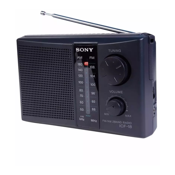
Sony ICF-18 Service Manual
Hide thumbs
Also See for ICF-18:
- User manual ,
- Operating instructions manual (6 pages) ,
- Operating instructions (2 pages)
Summary of Contents for Sony ICF-18
- Page 1 ICF-18 SERVICE MANUAL US Model Canadian Model AEP Model UK Model E Model Australian Model SPECIFICATIONS SECTION 1 GENERAL This section is extracted from instruction manual. FM/AM RADIO MICROFILM...
-
Page 2: Section 2 Disassembly
SECTION 2 DISASSEMBLY Note: Follow the disassembly procedure in the numerical order given. CABINET (REAR) 3 three claws 1 Remove the battery case lid to direction of the arrow. 5 screw (P 3 × 10) 2 two screws (P 3 × 14) 6 lug 4 cabinet (rear) KNOB (VOL), KNOB (TUNE) -
Page 3: Section 3 Dial Pointer Setting
SECTION 3 SECTION 4 DIAL POINTER SETTING ELECTRICAL ADJUSTMENTS Note: Follow the assembly procedure in the numerical order given. 0dB=1 µV FM FREQUENCY COVERAGE ADJUSTMENT Adjust for a maximum reading on level meter. [FM Section] 75.0 MHz Setting: 109.5 MHz Band select switch: FM Note: When take off the pointer, FM TRACKING ADJUSTMENT... - Page 4 ICF-18 SECTION 5 DIAGRAMS Note on Schematic Diagram: 5-1. SCHEMATIC DIAGRAM • IC Block Diagram • All capacitors are in µF unless otherwise noted. pF: µµF 50 WV or less are not indicated except for electrolytics and IC1 CXA1019S tantalums.
-
Page 5: Section 6 Exploded View
SECTION 6 EXPLODED VIEW NOTE: • -XX and -X mean standardized parts, so they • Items marked “*” are not stocked since they may have some difference from the original are seldom required for routine service. Some one. delay should be anticipated when ordering •... -
Page 6: Hardware List
SECTION 7 MAIN ELECTRICAL PARTS LIST NOTE: When indicating parts by reference • Items marked “*” are not stocked since they • Due to standardization, replacements in the number, please include the board. parts list may be different from the parts speci- are seldom required for routine service. -
Page 7: Accessories And Packing Materials
Ref. No. Part No. Description Remark ACCESSORIES & P ACKING MA TERIALS ******************************** 3-860-966-11 MANUAL, INSTRUCTION (ENGLISH, FRENCH, GERMAN , SPANISH, SWEDISH, PORTUGUESE, ARABIC, RUSSIAN) (EXCEPT US) 3-860-966-21 MANUAL, INSTRUCTION (ENGLISH) (US) 3-923-510-01 BEL T (SHOULDER) 3-925-458-01 STOPPER, BEL T –... - Page 8 ICF-18 Sony Corporation 97I0594-1 9-925-741-11 Personal & Mobile Communication Company Printed in Japan © 1997. 9 – 10 – Published by Quality Assurance Dept.


