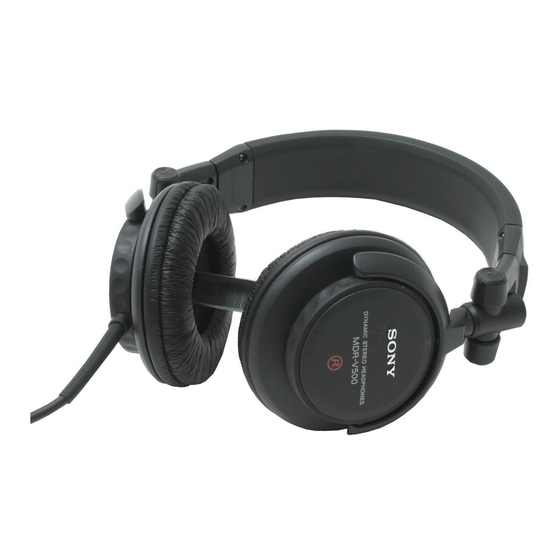
Sony MDR-V500DJ Service Manual
Stereo headphones
Hide thumbs
Also See for MDR-V500DJ:
- Operating instructions (4 pages) ,
- Specifications (21 pages) ,
- Limited warranty (1 page)
Advertisement
Quick Links
Download this manual
See also:
Operating Instructions
SERVICE MANUAL
REVISED
Ver 1.1 1999. 07
SPECIFICATIONS
Type
: Dynamic, Closed
Driver unites
: ø40 mm, dome type
Impedence
: 40
at 1 kHz
Sensitivety
: 102 dB/mW
Power handling capacity
: 1000 mW
Frequency response
: 10 – 25,000 Hz
Cord
: Coiled 1 – 3 m long single-sided OFC-litz cord
with a gold plated stereo unimatch plug
Mass
: Approx. 225 g (wihtout cord)
Design and specifications are subject to change without notice.
Features
• Monitoring headphones for DJ and remix use
• Swivel earcup allows easy single sided monitoring on shoulders
• 40 mm driver unit for high quality sound
• Coiled OFC litz cord
• Screw type gold plated stereo unimatch plug for secure
connection
• Convenient folding design
ACCESSORIE
Ref. No.
Part No.
Description
ACCESSORIES & PACKING MATERIALS
******************************
3-866-560-11 MANUAL, INSTRUCTION
MICROFILM
MDR-V500DJ
Remarks
(ENGLISH/FRENCH/GERMAN/SPANISH/
ITALIAN/PORTUGUESE/RUSSIAN)
Canadian Model
[WIRING DIAGRAM]
(RED)
(BRONZE)
Marking
DRIVER
DRIVER
(R)
(BRONZE)
(RED)
STEREO HEADPHONES
US Model
AEP Model
E Model
(BRONZE)
(RED)
Marking
(L)
(GREEN)
Advertisement

Summary of Contents for Sony MDR-V500DJ
- Page 1 MDR-V500DJ SERVICE MANUAL US Model Canadian Model REVISED AEP Model E Model Ver 1.1 1999. 07 SPECIFICATIONS [WIRING DIAGRAM] Type : Dynamic, Closed Driver unites : ø40 mm, dome type (BRONZE) (RED) Impedence : 40 at 1 kHz (RED) Marking...
-
Page 2: Section 1 Disassembly
SECTION 1 DISASSEMBLY Note : Disassemble the unit in the order as shown below. Driver (L side) Cord (with plug) Hunger (L) Driver (R side) Hunger (R) Note : Follow the disassembly procedure in the numerical order given. 1-1. DRIVER (L SIDE) 5 Remove the five solderings 6 Driver (headphone) (040F016) - Page 3 1-3. HUNGER (L) 2 Cushion stopper (upper) Precaution during installation Adjust the distance between the slider holder and harness to the specified distance as shown. Slider holder (L side) 1 Two screws (+P2 0 – 2 mm 3 Cushion stopper (lower) (L) Precaution during installation Route the harness into 4 Claw...
- Page 4 1-4. DRIVER (R SIDE) 5 Remove the two solderings 6 Driver (headphone) (040F016) 4 Rotate it in the direction of the arrow. 2 Three screws (+P2.6 Precaution during installation 1 Ear pad Driver (R side) 3 Front assembly plate Marking side Natural Harness —...
- Page 5 1-5. HUNGER (R) 4 Cushion stopper (upper) Precaution during installation Adjust the distance between the slider holder and harness to the specified distance as shown. 3 Two screws Slider holder (R side) (+P2 5 Cushion stopper (lower) (R) 0 – 2 mm 1 Two claws 1 Housing ring (R)
-
Page 6: Section 2 Exploded View
MDR-V500DJ SECTION 2 EXPLODED VIEW NOTE: • -XX, -X mean standardized parts, so they may have some differences from the original one. • The mechanical parts with no reference number in the exploded views are not supplied. not supplied (including 3) Ref.


