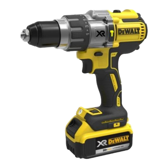
DeWalt DCD996 Service Training
Hide thumbs
Also See for DCD996:
- User manual ,
- Instruction manual (29 pages) ,
- Operating instructions manual (17 pages)
Summary of Contents for DeWalt DCD996
- Page 2 DCD996P2 DCD991P2 Description 18V XR BL Hammer Drill Driver 18V XR BL Drill Driver Chuck Capacity (mm) 1.5-13 1.5-13 Chuck Carbide Battery (Voltage) Power Output (Ah) 5.0Ah 5.0Ah Power Output (Unit Watts Hour) Load Speed (RPM) 0-450 / 1300 / 2000 (HD -0-500/1500/2250) 0-450 / 1300 / 2000 Beats per Minute 0-8600 / 25500 / 38250...
- Page 3 SET I = LOW Light LED LED with stay on for 20sec – 2.6 Lumens SET II = MEDIUM Light LED LED with stay on for 20sec – 18 Lumens SET III = HIGH 20min Light LED LED with stay on for 20min – 60 Lumens Set I Set II Set III...
- Page 4 ENGLISH GERMAN ITALIAN FRENCH SPANISH PORTUGUESE DUTCH CHECK ÜBERPRÜFEN CONTROLLARE CONTROLER COMPROBAR VERIFIQUE CONTROLEREN ATENÇÃO! ATTENTION ! ACHTUNG ATTENZIONE ATTENTION ! ATENCION ATTENTIE ! SWITCH ON ANSCHALTEN ACCENDERE ALLUMEZ ENCENDER LIGAR AANSCHAKELEN TOURNEZ DANS LE TURN DREHEN IN GIRARE IN SENSO GIRAR NO SENTIDO SENS DES AIGUILLES GIRO DERECHA...
- Page 5 ENGLISH GERMAN ITALIAN FRENCH SPANISH PORTUGUESE DUTCH … SEQUÊNCIA 1;2;3;4 SEQUENCE REIHENFOLGE SEQUENZA SEQUENCE SECUENCIA VOLGORDE DISCONNECT TRENNEN SCOLLEGARE DEBRANCHEZ DESCONECTADO DESLIGAR ONTKOPPELEN SERVICE OUTILLAGE DE HERRAMIENTAS DE FERRAMENTAS DE SERVICE SERVICE TOOL UTENSILE DI SERVIZIO WERKZEUG SERVICE SERVICIO SERVIÇO GEREEDSCHAP LUBRICATION BEFETTEN...
- Page 6 ENGLISH GERMAN ITALIAN FRENCH SPANISH PORTUGUESE DUTCH UTILISEZ UN USE STATIC GEBRUIK ANTI - ANTISTATIK MATTE USARE I DISPOSITIVI EQUIPEMENT DE USE PROTECCION USE PROTEÇÃO PROTECTION STATISCH BENUTZEN ANTISTATICI PROTECTION ANTIESTATICA ESTATICA DEVICE MATERIAAL ANTISTATIQUE CLEAN SÄUBERN PULIRE NETTOVER LIMPIAR KUISEN LIMPAR REMOVE...
- Page 7 Before repair and strip down Carry out a visual check: Condition of contacts (unit and battery) mode selector leakages condition of chuck Carry out a functionality check: percussion mechanism 3 gears / torque power settings reverse mode measure the capacity of batteries check condition of charger (use the charger to charge a obviously good battery and measure the capacity of the battery...
- Page 8 Understand how the E-Clutch works The electronic control module senses current Clutch Collar into the tool from the battery. When the tool is in clutch mode (or desired setting), the module senses a determined current value for a defined clutch setting and activates the clutch (thus clutching out and stopping the motor).
- Page 9 Understand how the E-Clutch works As highlighted in slide 9 , it is important to note that the motor will shut down at a defined current that is measured at the micro processor. In order to determine at which setting we are at a defined value of voltage is measured. To give an example : If we are at torque setting 6, it will detect this position by design, correct voltage will be measured.
- Page 13 2013 33-59 2013 33-59...
- Page 17 1/min 1. Ge 2.Gear 3.Gear 1336 69%) 69%) 68%) 1027 1527 (77%) 77%) 77%) 1114 1707 86%) 85%) 87%) 1320 1964 (100) - Drill (100) (100)
- Page 19 2016 17-59...
- Page 22 DCD991...
- Page 23 DCD996...
-
Page 24: Electrical Check
ELECTRICAL CHECK Remove housing and gear case screws, opening up and removing cover side handle. Carefully remove Transmission Front End and Module/Motor together as one full unit. - Page 34 Component Identification SA Front End Brushless Motor Forward/Reverse Bar Module Switch PCB Terminal Block...
- Page 35 Inspect all wires for pinches, nicks, or cuts. Anything abnormal can effect function. Please check the electrical inputs and outputs from Clutch Position Sensor (CPS)
- Page 36 Pinch Point: Connector must be fully seated Pinch Point: CPS wires between the screw boss and gear case Pinch Point: CPS wires into the screw boss Pinch Point: Hall wires to housing Pinch Point: LED wires to housing and PCBs...
-
Page 37: Functional Check
FUNCTIONAL CHECK: To better diagnose our new eClutch and related sensors. We have assembled an initial diagnostic flowchart to better pinpoint the root cause of a potential customer complaint. A customer may come in with a complaint that the drill is drilling in clutch mode or clutching out in drill (or hammer) mode. - Page 38 Diagnostic Flowchart DCD991 / DCD996 eClutch Put Drill in Clutch #1, Speed 3 and pull the trigger, hold for 2 seconds.
- Page 39 Diagnostic Flowchart DCD991 / DCD996 eClutch...
- Page 40 Diagnostic Flowchart DCD991 / DCD996 eClutch...
- Page 41 Power Wire (RED) Ground Wire (BLK) LED on indicates power to Sensor...
- Page 43 Clutch Ω ±1% Setting 2000 4000 5870 7740 9790 12600 16400 21040 27380 37140 50140 DRILL 72240 HAMMER 106240...
- Page 45 Occasionally the pins will get bent down and slide under the mating connector instead of into. Inspect units for this, and be sure not to do this. Connector pins should be pushed fully into connector body.
- Page 47 TX10 3X10...
- Page 53 559661-99 596004-99...
- Page 56 Assembling Gear- Housing...
- Page 57 Assembling Gear- Housing...
- Page 58 Assembling Gear- Housing...
- Page 59 Assembling Gear- Housing...
- Page 60 Assembling Gear- Housing...
- Page 61 Assembling Gear- Housing...
- Page 62 Assembling Gear- Housing TX10 3X10...
- Page 63 After repair 1/min 1. Ge 2.Gear 3.Gear 1336 69%) 69%) 68%) 1027 1527 (77%) 77%) 77%) 1114 1707 86%) 85%) 87%) 1320 1964 (100) - Drill (100) (100)
- Page 64 WWW.2HELPU.COM...
- Page 65 Remember: the next check will be made by your customer...


