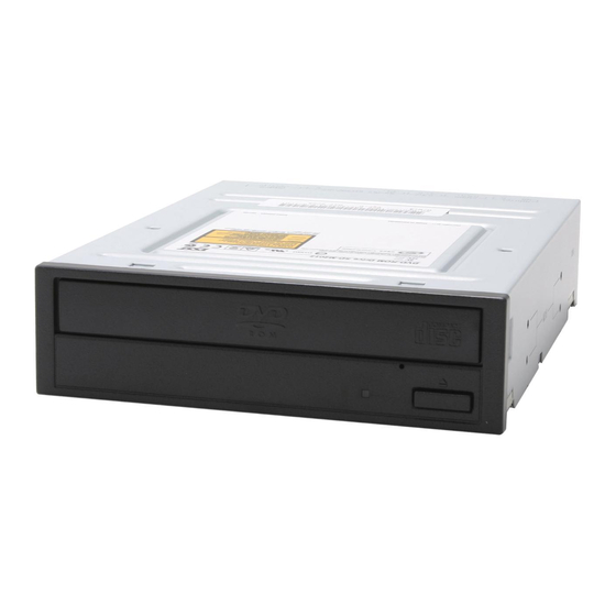
Summary of Contents for Toshiba SD-M2012C
- Page 1 TOSHIBA AMERICA INFORMATION SYSTEMS STORAGE DEVICE DIVISION IRVINE, CALIFORNIA SD-M2012C DVD-ROM DRIVE USER MANUAL...
-
Page 2: Table Of Contents
CONTENTS Introduction...1 Setup ...3 Using the DVD-ROM Drive ...6 Troubleshooting...9 Specifications ...10 Drive Connectors...13... -
Page 3: Introduction
INTRODUCTION – SD-M2012C DVD-ROM Drive General Features Tray Loading Mechanism 3-way Disc Eject (eject button, software, emergency eject hole) Average Random Access Time CD-ROM 110ms CD-RW 170ms DVD - single 110ms DVD – Dual 150ms DVD-RAM 200ms DAE (Digital Audio Extraction) Audio Capability... - Page 4 • CD-R (Read) • CD-RW (Read) Front Panel Figure 1.SD-M2012C DVD-ROM Drive Front Panel Load disc using tray. Loading Tray When you install a disc into the DVD-ROM drive, the BUSY light flashes slowly as it Busy Indicator attempts to locate the disc. One of the following will occur: •...
-
Page 5: Setup
SETUP – SD-M2012C DVD-ROM The following steps must be performed to properly install your drive: • Set Drive Jumper Settings • Connect Audio Cable (optional) • Attach IDE BUS Cable • Attach Power Cable • Mount Drive Jumper Settings The mode select jumpers are 6 straight angle pins located on the rear of the DVD-ROM drive. - Page 6 If the DVD-ROM drive is replacing a CD-ROM or DVD-ROM, remove drive presently installed in your system. Your Toshiba DVD-ROM drive can be placed in any free half-height drive slot at the front of your computer. (It can be mounted horizontally or vertically.) Carefully start sliding the DVD-ROM drive into the opening with the disc tray facing the front of the computer.
- Page 7 Figure 6.Mounting Illustration Software Driver - Toshiba's optical drives do not require any unique device drivers for Windows '95/'98/2000/Me/XP/NT. After installing your drive and re-booting, your system should recognize your drive. Windows '95/'98/2000/Me/XP/NT Operating Systems support all Toshiba optical drives natively If...
-
Page 8: Using The Dvd-Rom Drive
USING THE DVD DVD-ROM Drive – SD-M2012C Drive Operation Inserting a Disc - Horizontally To insert a disc into a drive that is mounted horizontally, perform the following steps: Figure 1.Inserting Disc 1. Open the drive's Loading tray by pressing the Eject Button. - Page 9 Removing a Disc To remove a disc from the DVD-ROM drive, perform the following steps: 1. Open the Loading Tray by pressing the Eject Button. 2. Grasp disc by edges, and lift out of loading tray. 3. Press Eject Button again to close Loading Tray. Usage Guidelines •...
- Page 10 NOTE: Use a bar that is less than 1.5 mm in diameter. Do not insert more than 50mm in depth. Inserting more than 50mm may damage the DVD-ROM drive. Handling Media DVD media is sensitive to dust and fingerprints. Carefully handle media by its edges only. If a DVD movie skips or hangs during playback, clean the media.
-
Page 11: Troubleshooting
TROUBLESHOOTING – SD-M2012C Problem Disc tray cannot be opened Drive is not recognized by system Drive is not recognized by system during Boot process, recognized Operating System (i.e. XP, Win2000, Win98, Win NT, etc.) BUSY Indicator LED flashes slowly BUSY Indicator LED is constantly... -
Page 12: Specifications
SPECIFICATIONS –SD-M2012C General Interface ATAPI Media Compatibility 120mm CD-ROM (Read Only) 80mm CD (Horizontal Mount Only) 800/700/650/550MB CD-Recordable (Read) 80mm CD- Recordable (Read / Horizontal Mount Only) 700/650MB CD-Rewritable (Read) 700/650MB High Speed CD-Rewritable (Read) Ultra Speed CD- Rewritable (Read) - Page 13 Burst Rate Random Access Time CD-ROM CD-RW DVD-Single DVD-Dual DVD-RAM Data Error Rate Spin-up Time CD/DVD Data Buffer Audio Number of Channels Frequency Response Distortion Output Levels Environmental Ambient Temperature Operating Storage Relative Humidity Operating Storage/Shipping Vibration Operating Non-operating Shock (Non-operating) Acoustical Noise 16.7 Mbyte/s (PIO Mode 4) 16.7 Mbyte/s (multiple word DMA transfer mode 2)
- Page 14 Connectors DC input IDE Interface Connector Analog Audio Line Output Connector Digital Audio Line Output Connector Regulatory The SD-M2012C DVD-ROM drive has been certified by the following regulatory agencies: • UL 1950 • CSA C22.2 No. 950 • TUV (EN60950I) •...
-
Page 15: Drive Connectors
CAUTION: Severe damage to the Drive circuits may occur if power cable is plugged in upside- down with power ON. Audio Connectors Supplies Analog and Digital sound to your system. ATAPI The SD-M2012C DVD drive is connected to your computer system through the ATAPI connector. Connector... - Page 16 Table 1.Interface Pin Assignments SIGNAL HOST SIGNAL NAME NAME Reset Host Reset Host Data Bus BIT 7 Host Data Bus BIT 8 Host Data Bus BIT 6 Host Data Bus BIT 9 Host Data Bus BIT 5 HD10 Host Data Bus Bit 10 Host Data Bus BIT 4 HD11 Host Data Bus BIT 11...


