Table of Contents
Advertisement
Quick Links
SERVICE MANUAL
VF-P115BU/VF-P115BE
DIFFERRENCES BETWEEN VF-P115B AND VF-P115
Page
Symbol
No.
4-2
1
4-2
28
4-2
46
4-2
51
4-2
57
3-1
—
3-1
—
VICTOR COMPANY OF JAPAN, LIMITED
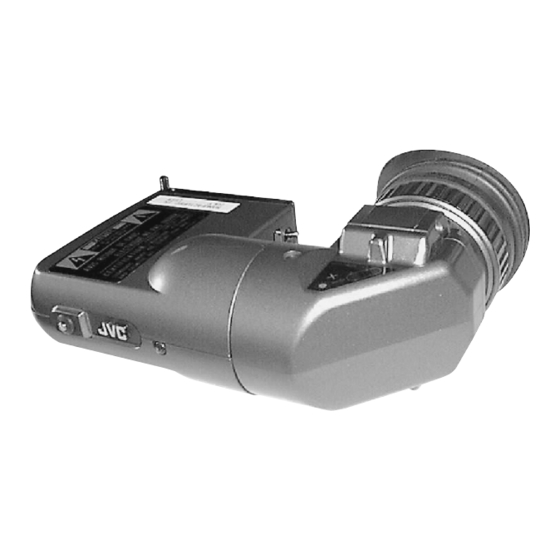
VIEWFINDER
Part Name
UPPER CASE
SC20415-011
BOTTOM CASE
SC20418-021
MIRROR CASE
SC20336-021
LENS HOLDER
SC31041-021
LOCK RING
SC43458-021
Instructions (U)
SC96895
Instructions (E)
SC96895
COPYRIGHT © 1999 VICTOR COMPANY OF JAPAN, LTD.
NOTE:
•
This service manual only describes the
matters that are different from the VF-
P115.
On servicing, refer to the service manual
(No. 60033) for the VF-P115 together with
this.
Part No.
VF-P115B
VF-P115
SC20415-001
SC20418-011
SC20336-011
SC31041-012
SC43458-011
SC96502
SC96503
No. 60126
Octorber 1999
Advertisement
Table of Contents

Summary of Contents for JVC VF-P115BU
- Page 1 SERVICE MANUAL VIEWFINDER VF-P115BU/VF-P115BE NOTE: • This service manual only describes the matters that are different from the VF- P115. On servicing, refer to the service manual (No. 60033) for the VF-P115 together with this. DIFFERRENCES BETWEEN VF-P115B AND VF-P115...
-
Page 2: For Usa And Canada
Model No. VF-P116W Serial No. SC96839 Thank you for purchasing the JVC VF-P116W Viewfinder. To WARNING: gain maximum benefit from the viewfinder, it is suggested TO REDUCE THE RISK OF FIRE OR ELECTRIC that you study this booklet carefully. After reading, retain it for SHOCK, DO NOT EXPOSE THIS APPLIANCE future reference. -
Page 3: Controls, Indicators, Connectors
PRECAUTIONS ● Before attaching the VF-P116W, be sure to read the instruc- ● Strong electromagnetic waves or magnetism (for example, tion manual of the color video camera to which it is to be near a radio or TV transmission antenna, transformer or mo- connected. -
Page 4: Troubleshooting
EYEPIECE Blocks light from viewfinder screen and holds eye optics. The Eyepiece can be opened to view the screen directly. The Eyepiece can be rotated up and down for the best shooting position. EYEPIECE FOCUSING RING Loosen this ring and move the Eyepiece backward and forward to focus the viewfinder for the operators vision. -
Page 5: Specifications
SPECIFICATIONS Input signal : Composite video, 1 Vp-p, high impedance : 38 mm (1.5") diagonal Resolution : More than 600 lines (aspect ratios : 4 : 3) Aspect ratios : 4 : 3 or 16 : 9 (switched automatically by a signal from the camera.) Indications : Tally;... - Page 6 SECTION 3 CHARTS AND DIAGRAM UNLESS OTHERWISE SPECIFIED Voltage and waveform weasurements. PNP TRANSISTORS : MSA1022(C) ・Voltage : Measured with digital volt meter 3.1 VF-P116W SCHEMATIC DIAGRAM NPN TRANSISTORS : MSC2295(C) in DC range, iris closed. ・Waveform ...
-
Page 7: Circuit Boards
CIRCUIT BOARDS MAIN BOARD Description of New Circuit 4:3/16:9 switching SIDE B The 4:3/16:9 switching signal from the camera is input through pin 5 of the VF connector. The input voltage is 0 V ( L ) for 4:3 and ... -
Page 8: Section 4 Exploded View And Parts List
4.1 VF-P116(A) ASSEMBLY SAFETY PRECAUTION Parts identified by the ! symbol are critlcal for safety. Replace only with speclfled parts numbers. NOTE Parts not denoted by parts numbers are not supplled by JVC. TOP TALLY BOARD MAIN BOARD VF BOARD... - Page 9 VF-P116(A) ASSEMBLY PARTS LIST M 1 M M ` ` ` ` Symbol Symbol Part No. Part Name Description Part No. Part Name Description 1 SC31312-012 CRT HOLDER1 S4 QYSDSP2005Z SCREW M2 x 5 2 SC31312-011 CRT HOLDER S6 QYSPSA2006M SCREW M2 x 6 3 SCV1273-001...
- Page 10 SECTION 6 PACKING INSTRUCTIONS SC96985 Cushion SHEET Cushion Carton box Note: Accessories above are subject to change without notice.
-
Page 11: Safety Precaution
2.2M 1/10W Q108 MSC2295/C/-X TRANSISTOR MOTOROLA R162 NRSA02J-225X M.G.RESISTOR 2.2M 1/10W ● Parts not denoted by parts numbers are not supplled by JVC. Q109 MSB709/R/-W TRANSISTOR MOTOROLA R163 NRSA02J-332X M.G.RESISTOR 3.3k 1/10W ● Abbreviations in this list are as follows:... - Page 12 5.2 VR BOARD ASSEMBLY PARTS LIST 0 2 ` ` ` ` ` ` SCK2554-02-00A Symbol Symbol Part No. Part Name Description Part No. Part Name Description C109 QETM1HM-336 E.CAPACITOR R201 NRSA02J-684X M.G.RESISTOR 680k 1/10W R202 NRSA02J-824X M.G.RESISTOR 820k 1/10W C110 NCB11CK-105X CER.CAPACITOR...


