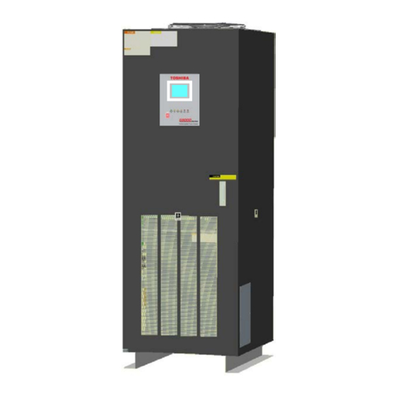
Toshiba G9000 SERIES Installation And Operation Manual
480/480 v
100/160/225 kva
Hide thumbs
Also See for G9000 SERIES:
- Installation and operation manual (104 pages) ,
- Installation manual (24 pages) ,
- Manual (18 pages)

Related Manuals for Toshiba G9000 SERIES


Summary of Contents for Toshiba G9000 SERIES
- Page 1 UNINTERRUPTIBLE POWER SYSTEM (UPS) G9000 SERIES G9000 ENHANCED SERIES UPS INSTALLATION AND OPERATION MANUAL 480/480 V 100/160/225 kVA Doc. No.: 93823-004 Reference: 4GBH0094 Rev. E December 2015...
- Page 2 G9000 Enhanced Series UPS Installation and Operation Manual – 93823-004...
- Page 3 G9000 SERIES G9000 ENHANCED SERIES UPS INSTALLATION AND OPERATION MANUAL 480/480 V 100/160/225 kVA Document. No. 93823-004 Reference No. 4GBH0094 Rev. E December 2015 G9000 Enhanced Series UPS Installation and Operation Manual – 93823-004...
- Page 4 G9000 Enhanced Series UPS Installation and Operation Manual – 93823-004...
-
Page 5: Important Notice
The sales contract contains the entire obligation of TOSHIBA INTERNATIONAL CORPORATION. The warranty contained in the contract between the parties is the sole warranty of TOSHIBA, and any statements contained herein do not create new warranties or modify the existing warranty. -
Page 6: Purpose And Scope Of Manual
TOSHIBA shall not be liable for technical or editorial omissions or mistakes in this manual. Nor shall it be liable for incidental or consequential damages resulting from the use of information contained in this manual. -
Page 7: Table Of Contents
Table of Contents List of Figures ..............................ii List of Tables ..............................iv How to use this Manual.......................... 1 INTRODUCTION ........................... 2 SAFETY PRECAUTIONS ......................3 GENERAL .............................. 6 DEFINITIONS..........................7 OPERATION OVERVIEW ......................8 3.2.1 Normal Operation: Load power supplied by each system UPS inverter........8 3.2.2 Bypass Operation: Load Power supplied through UPS internal static bypass line. -
Page 8: List Of Figures
List of Figures Figure 3-1 Single Line Diagram – Normal Operation: Load fed by UPS inverter ........8 Figure 3-2 Single Line Diagram – Bypass Operation: Load fed through static bypass line ....9 Figure 3-3 Single Line Diagram – Battery Operation – Load fed by Battery ........10 Figure 3-4 Single Line Diagram –... - Page 9 Figure 5-6 Cable Entry on Bottom (Example of 225kVA) ..............45 Figure 5-7 Cable Entry on Top (Example of 225kVA) ................45 Figure 5-8 Circuit Protectors Location ....................46 Figure 5-9 Automatic Startup of Inverter and Converter ............... 47 Figure 5-10 Close Battery Breaker ....................... 47 Figure 5-11 Press and Hold START Button..................
- Page 10 List of Tables Table 2–1 UPS Installation Environment ....................4 Table 2–2 Rating of Bypass Input Circuit Breaker .................. 5 Table 3–1 Power Specifications ......................14 Table 3–2 UPS Module Information (Overall Dimension) ..............14 Table 3–3 UPS Module Information (Packing Dimension) ..............14 Table 3–4 Specifications ........................
-
Page 11: How To Use This Manual
NEVER perform during the UPS installation, operation or service work. PROHIBIT Safety Recommendations: If any problems are encountered while following this manual, Toshiba field service group assistance and correspondence is recommended. G9000 Enhanced Series UPS Installation and Operation Manual – 93823-004... -
Page 12: Introduction
INTRODUCTION The Toshiba Uninterruptible Power Supply System (UPS) is designed to provide many years of reliable protection from power failure, brown-outs, line noise, and voltage transients. To ensure optimum performance of the equipment, follow the manufacturer's instructions. This manual contains descriptions required to operate the UPS. -
Page 13: Safety Precautions
WARNING 2 CAUTION In no event will TOSHIBA be responsible or liable for either indirect or consequential damage or injury that may come from the misuse of this equipment. Don’t modify the UPS entirely or partially. Any modifications without authorization by TOSHIBA could result in personal injuries, death or destruction of the UPS. -
Page 14: Table 2-1 Ups Installation Environment
WARNING 3 NOTE The UPS is to be installed in a controlled environment. Improper storage and installation environment may deteriorate insulation, shorten component life and cause malfunctions. Keep the installation environment per standard described as follows: Table 2–1 UPS Installation Environment Item Environment standard Installation... -
Page 15: Table 2-2 Rating Of Bypass Input Circuit Breaker
WARNING 4 NOTE This UPS does not include a Bypass input circuit breaker (MCCB) to protect the bypass circuit. The Bypass input circuit breaker (MCCB) is to be field supplied and installed. Recommended Breaker (MCCB)'s Specifications are as follows: Table 2–2 Rating of Bypass Input Circuit Breaker Capacity (kVA) Bypass Voltage (Vac) Bypass Rating (Aac) Breaker (A) AC input and AC output overcurrent protection and disconnect devices shall be field supplied and... -
Page 16: General
GENERAL The Toshiba G9000 UPS is designed to provide continuous and clean electrical power to a critical load. Additionally the UPS monitors power conditions affecting the load. In the event of an input power failure, the UPS will supply power to the critical load for the specified battery time. -
Page 17: Definitions
DEFINITIONS UNINTERRUPTIBLE POWER SUPPLY SYSTEM (UPS) – All components within the UPS Module Cabinet and associated batteries that function as a system to provide continuous, conditioned AC power to a load. This is sometimes referred to as the "System". UPS MODULE CABINET – The metal enclosure which contains the Converter / Charger, Inverter, Static Transfer Switch, Internal Bypass line, operator controls, and internal control systems required to provide specified AC power to a load. -
Page 18: Operation Overview
OPERATION OVERVIEW The UPS provides two power paths between the utility source and the critical load. Figure 3-1 shows the path for normal operation, with the load powered by the inverter. Figure 3-2 shows the path for bypass operation, with the load supplied through the static bypass line. Figure 3-3 shows the path for battery operation, with the load powered by the inverter. -
Page 19: Bypass Operation: Load Power Supplied Through Ups Internal Static Bypass Line
In the event of a UPS module failure during Parallel Operation, the critical load power will be continually supplied and shared by all other UPS. The Bypass Input breaker and cables are to be supplied and installed by the user or the constructor. -
Page 20: Battery Operation: Load Power Supplied By Ups Battery
In the event of a load overcurrent, the UPS transfers to bypass without interruption to the critical load. In the case of the Parallel Operation, all UPS will transfer to bypass without interruption to the critical load. The internal control system determines the operation of the two paths, with the load powered from the inverter being the normal operation. -
Page 21: Standby Mode Operation: Load Power Supplied Through The Ests. (Option)
When power is restored after a low battery shutdown, the UPS converter(s) automatically restarts operation, the charger(s) recharges the batteries and the Inverter(s) is automatically restarted without operator intervention. Load is automatically assumed by the inverter without operator intervention. * (s) : In the case of the Parallel Operation The power drawn by the load is equally shared between all UPS regardless of the presence or absence of the UPS that is (are) in battery operation or not whenever the system is in the Parallel Operation. -
Page 22: Ups Parts Location
3.2.5 UPS Parts Location Figure 3-5 Figure 3-6 for parts location in the UPS. 88RC FM1 (Fan) Parallel I/F PCB: IFAU-08C (Option) Power Supply PCB: PSAU-80 Inverter, Converter, LCD touch panel Charger Unit monitor display Display PCB: DPAU-81 Main PCB: UPGR-MC ESTS Unit (Option) Parallel control PCB: CPMC/CPMS/EMB... -
Page 23: Figure 3-6 Ups Parts Location (225 Kva)
FM1 (Fan) 88RC Parallel I/F PCB: IFAU-08C (Option) Power Supply PCB: PSAU-80 Converter and Charger Unit LCD touch panel monitor display ESTS Unit (Option) Display PCB: DPAU-81 Inverter Unit Parallel control PCB: CPMC/CPMS/EMB TLCR-CB (Option) Sensor PCB: VSAU-51 External I/F PCB: IOAU-09 STS Unit Grounding Bar (E) * Refer to Figure 5-2 for details of AC input, AC output, DC input terminals... -
Page 24: Specifications
SPECIFICATIONS The UPS nameplate displays the rated kVA as well as nominal voltages and currents. The nameplate is located on the inside of the UPS front door. Table 3–1 Power Specifications Bypass input Rated output Input voltage Output voltage voltage Power 3 phase / 3 wire 3 phase / 3 wire... -
Page 25: Table 3-4 Specifications
Table 3–4 Specifications Rated Output kVA Rated Output kW 202.5 AC INPUT Configuration 3 phase, 3 wire Voltage 480 V (+15% to -20%) Frequency 60 Hz ±10% Reflected Current THDi 3% typ. at 100% load (no input filter required) STATIC BYPASS INPUT Configuration 3 phase, 3 wire 480 V ±10%... -
Page 26: Table 3-5 Typical Ac-Ac Ups Efficiencies At Various Loads
Rated Output kVA Audible Noise 70 dB @ 1 m Listings/Standards UL; cUL; FCC Class A-Article 47 – Part 15 B; ISO 9001; ISO14001; ANSI C62.41 (IEEE 587 Cat. B) Warranty 3 Years Parts and Labor Emergency Power Off Included MONITORING Dry Contacts Included Yes, for Input and Output Signals... -
Page 27: Table 3-7 Rating Of Contactors, Breakers, And Fuses
Table 3–7 Rating of Contactors, Breakers, and Fuses OUTPUT CAPACITY OF EQUIPMENT 100 kVA 160 kVA 225 kVA NUMBER APPLICATION 90 kW 144 kW 202.5 kW AC input contactor 135 A 200 A 260 A STS contactor 135 A 200 A 260 A Inverter output contactor 135 A... -
Page 28: Operator Controls And Indicators
OPERATOR CONTROLS AND INDICATORS The G9000 Enhanced Series operator controls and indicators are located as follows (Door exterior) : Figure 4-1 Operation/Display Panel (Front panel) G9000 Enhanced Series UPS Installation and Operation Manual – 93823-004... -
Page 29: Led Display
LED DISPLAY 1) Load on inverter [ LOAD ON INVERTER ](green) Illuminates when power is supplied from inverter to the critical load. (Indicates the state of inverter transfer switch "52C".) 2) Battery operation [ BATTERY OP. ] (yellow) Illuminates when power is supplied from batteries following a power failure. 3) Load on bypass [ LOAD ON BYPASS ] (yellow) Illuminates when power is supplied to load devices by static bypass. -
Page 30: Menu
4.3.1 Menu A) MAIN MENU (Figure 4-2) The LCD panel indicates power flow and measured values, while also operating the start/stop function. The LCD panel also allows the user to verify the status and operation of the UPS Module. Figure 4-2 Main Screen The following will be displayed when the START/STOP key on the MAIN MENU is pressed (Jump into OPERATION MENU) : Startup/Shutdown Guidance (Figure 4-3 to Figure 4-5) -
Page 31: Figure 4-3 Startup/Shutdown Screen
Figure 4-3 Startup/Shutdown Screen Figure 4-5 Shutdown Guidance Figure 4-4 Startup Guidance Follow Startup/Shutdown guidance accordingly. MEASUREMENT MENU (Figure 4-6 to Figure 4-8) This screen shows details of measured values. Input and Output values are displayed. During Battery operation, Remaining battery power and Run time are also displayed. Figure 4-6 Input Values G9000 Enhanced Series UPS Installation and Operation Manual –... -
Page 32: Figure 4-7 Output Values
Figure 4-7 Output Values Figure 4-8 Values in Battery operation C) OPERATION MENU (Figure 4-9 and Figure 4-10) This screen prompts the user to select: (a) whether the start & stop operation will be performed by local or remote operation; (b) date & time adjustment; (c) battery equalizing charge. The battery equalizing charge operation key will appear when battery equalizing charge is set up (Setup is based on battery type). -
Page 33: Figure 4-11 Log Menu
Figure 4-11 Log Menu Figure 4-12 Event Log Figure 4-13 Battery Log G9000 Enhanced Series UPS Installation and Operation Manual – 93823-004... -
Page 34: Input Power Failure
4.3.2 Input Power Failure During an Input Power Failure, the UPS inverter will be powered by the UPS batteries. The following will be displayed on the main and measurement screen (Indication of battery operation and remaining battery time). Figure 4-14 Main Screen (Battery Operation) Figure 4-15 Measurement Screen (Battery Operation) The LCD will display a battery low voltage message when the battery capacity is near depletion. -
Page 35: External Signal Terminal Block
1) MESSAGE The display shows a fault code, the description of the fault and a guidance of what action is to be taken by the user. A maximum of 10 faults are displayed at one time. If an input power failure occurs during a fault condition, the fault indication and input power failure announcement are alternatively displayed at 5 second intervals. -
Page 36: Figure 4-18 Control Wiring For Aux Input Contacts
A) Input Contacts (for remote access of UPS) Input terminal provides four (N1 – N4) programmable contacts that can be set to any of the functions in . External contacts are provided by the user of the UPS system. Terminal voltage at the UPS is 24VDC. Provide external dry contact accordingly. -
Page 37: Figure 4-19 External Signal Terminal Block - Tn1 (Nec Class2)
The UPS is equipped with programmable input contact parameters. The above items are the default settings. Contact Toshiba International Corporation for setup information. NOTE The input logic can be reversed by setting the Active Level to "Neg" when selecting the input function. -
Page 38: Table 4-1 External Input Functions
CB1 ON IL Stops the rectifier converter remotely. TRACE TRIGGER For use with the internal wave capture tool; for use by Authorized Toshiba Service Providers. *Default Settings from Factory. G9000 Enhanced Series UPS Installation and Operation Manual – 93823-004... -
Page 39: Output Contacts (For External Alarm Annunciation)
4.4.2 Output Contacts (for external alarm annunciation) Output contacts consist of form “A”(NO) dry type contacts. Rated capacity of all output contacts is NEC Class2 (30Vdc/1Adc). All dry contacts should be operated at their rated values or lower. Figure 4-20 illustrates a typical installation. -
Page 40: Table 4-2 Tn2 Output Contact Alarm Programming Options
Activated when the battery voltage drops below Discharge Warning Voltage Level 2 during inverter operation. This level is set in the TEST MENU by an Authorized Toshiba Service Provider. This is the default setting for OUT5. BATTERY DEPLETION Activated when the battery voltage drops below discharge end voltage level during inverter operation. -
Page 41: Remoteye 4 Introduction
(provided with RemotEye) Cable1 DPAU-81 (provided) (SW1) RemotEye 4 Figure 4-22 RemotEye 4 Configuration “ ” RemotEye 4 * Consult Toshiba International Corporation for details on monitoring software and its capabilities. G9000 Enhanced Series UPS Installation and Operation Manual – 93823-004... -
Page 42: Figure 4-23 Connection Between Display Control Pcb (Sw1) And Remoteye 4 Module
The Power Supply PCB (PSAU-60, designated as PS1) and the Cable1 (designated as 3BBA0083P001) are equipped with G9000 UPS units. The Cable2 (D-sub 9pin) and the Cable3 (12V power cable) are included in the RemotEye 4 package. The Power Supply PCB (PS1) provides connectivity between the Display Control PCB (DPAU-81, designated as SW1) and the RemotEye 4 module in G9000 UPS units. -
Page 43: Figure 4-24 Psau-60 Pcb (Ps1)
The parts (included RemotEye 4) for UPS monitoring are listed below. Table 4–3 Parts List for UPS Monitoring Parts No. Part name Qt’y Power supply PCB (PS1): PSAU-60* Cable1: 3BBA0083P001 RemotEye 4 module Cable2: D-sub 9-pin to RJ45 Cable Cable3: 12V Power Cable * –... -
Page 44: Connector Definition
CONNECTOR DEFINITION Description Pin 1 Not used Pin 2 Receive Data Pin 3 Transmit Data Pin 4 Not used Pin 5 Signal Ground Pin 6 Not used Pin 7 Not used Pin 8 Not used Pin 9 Not used D-SUB 9Pin (male) Figure 4-27 Connector (CN1) of PSAU-60 (PS1) Description Pin 1... -
Page 45: Installation And Operation
INSTALLATION AND OPERATION TRANSPORTATION AND INSTALLATION Table 5–1 How to Transport and Install the System Transportation Installation Transport unit with forklift. Using the pre-drilled four holes in the UPS If carry by overhead crane, use four M12 channel base, anchor the unit using eyebolts. -
Page 46: Procedure For Cable Connections
D) External Battery Supply Please refer to the following when installing and maintaining batteries: 1. The customer shall refer to the battery manufacturer's installation manual for battery installation and maintenance instructions. 2. The maximum permitted fault current from the remote battery supply, and the DC voltage rating of the battery supply over-current protective device are shown in NOTE Table 5–3. - Page 47 After the completion of the input power cables connection: With a phase rotation meter, check that the phase rotation of the AC Input power terminals A, B and C as well as the Bypass Input power terminals A40, B40 and C40 are →...
- Page 48 Control wire connection Parallel configuration wiring (Refer to Figure 5-4 and Figure 5-5) 52L control signal from Toshiba Tie Cabinet (TTC) to UPS-n IOAU-09 (TN1– 5 , 6). - Parallel control signal for CN94 as shown in Figure 5-5.
-
Page 49: Table 5-4 Recommended Cable Sizes
Table 5–4 Recommended Cable Sizes Input Side Output Side Bypass Side DC Input Side Input Output Cable Torque Cable Torque Cable Torque Cable Torque Capacity Voltage Voltage Size ft. lbs Size in. lbs Size in. lbs Size in. lbs 2/0 AWG – 17-22 2/0 AWG –... -
Page 50: Figure 5-1 Ups Terminal Designations
Table 5–5 Crimp Type Compression Lug WIRE WIRE RECOMMENDATION CRIMP TOOL REQUIRED SIZE STRAND BURNDY TYPE Y35 OR Y46 (CODE) CLASS VENDOR CAT. NO. COLOR KEY DIE INDEX 1 AWG BURNDY YA1C GREEN 11 / 375 ILSCO CRA-1L GREEN 11 / 375 BURNDY YA25-LB 1019... -
Page 51: Figure 5-2 Input/Output Bus Bars And Terminal Blocks
Location of bus bars and terminal blocks (Bottom Entry) Detailed Power Terminals (A-A’) H=80.7” (2048.6 mm) D=32.7” (830 mm) 225kVA :35.4” (900 mm) For power terminals, use 1/2” (12 mm) Diameter bolts. 100kVA and 160kVA:27.6” (700 mm) Rear UPS module UPS module External Block... -
Page 52: Figure 5-3 Power Wire & Control Wire Inter-Connect Between Ups And Battery
DC Breaker for Battery Figure 5-3 Power Wire & Control Wire Inter-Connect between UPS and Battery G9000 Enhanced Series UPS Installation and Operation Manual – 93823-004... -
Page 53: Figure 5-4 Power Wire Connections (Parallel System Configuration)
Toshiba Tie Cabinet (TTC) UPS-1 52MB Bypass Maintenance Bypass input Bypass Breaker Converter /Charger Inverter AC input AC output 52L1 Breaker Battery UPS-2 Bypass Bypass input Output Breaker Converter 52CS /Charger Inverter AC input AC output 52L2 Breaker Battery UPS-n... -
Page 54: Figure 5-5 Power Wire & Control Wire Connections For 4 Units In Mms Configuration
CBOUT Use Ethernet STP CAIN OUTPUT (Shielded Twisted CAOUT Pair) Cable for all communication cabling. Use of UTP (Unshielded Twisted UPS-2 Toshiba Tie Cabinet (TTC) IOAU-09 Pair) Cable may IFAU-08 cause malfunction. CN96 TLIN CN95 TLOUT 52L1-AX CN94 52L2-AX CBIN... -
Page 55: Figure 5-6 Cable Entry On Bottom (Example Of 225Kva)
IOAU-09* RED=LOW VOLTAGE FIELDS WIRINGS BLUE=HIGH VOLTAGE FIEDLS WIRINGS Figure 5-6 Cable Entry on Bottom (Example of 225kVA) RED=LOW VOLTAGE FIELDS WIRINGS IOAU-09* Figure 5-7 Cable Entry on Top (Example of 225kVA) G9000 Enhanced Series UPS Installation and Operation Manual – 93823-004... -
Page 56: Operating Procedures
OPERATING PROCEDURES NOTE: To avoid inadvertently placing the UPS online or offline the START and STOP switches must be pressed and held for a period of several seconds to execute the command. • START – Press and hold the START switch for approximately 2 seconds. •... -
Page 57: Figure 5-9 Automatic Startup Of Inverter And Converter
f.) FOR GUIDANCE IN STARTING THE UPS, select “OPERATION” tab on the LCD panel, then press the “STARTUP GUIDANCE” icon (Figure 4-3) and follow the on-screen directions to continue UPS start-up (Figure 4-4). (The directions are the same as given in the following steps.) OR remain on the “MAIN”... -
Page 58: Figure 5-11 Press And Hold Start Button
Figure 5-11 Press and Hold START Button When "REMOTE OPERATION MODE" is displayed on the LCD panel, the inverter start operation can only be performed remotely. If local inverter start operation is required (at the UPS), select "LOCAL ONLY" or “REMOTE & LOCAL” in the OPERATION MENU. NOTE G9000 Enhanced Series UPS Installation and Operation Manual –... -
Page 59: Figure 5-12 Transfer From Online To Bypass
B) Transfer from Online to Bypass Procedure Transfer to Bypass to remove power from the inverter but continue to provide utility power to the critical load. a.) Press the "START/STOP" icon from the “MAIN” Menu on the LCD. b.) On the LCD panel, press and hold STOP for five (5) seconds. (Figure 5-11a) c.) The UPS transfers to Bypass. -
Page 60: Figure 5-14 Initiate Shutdown
D) Shut-down Procedure If a total UPS shutdown is required, verify that the critical load is OFF. Verify the load is OFF if the next step is to be performed. Power to the load has been supplied through the bypass line. Power to load will be lost after execution of the next step. -
Page 61: Figure 5-16 Open Battery Breaker
In bypass mode, all UPS power terminals are still alive. Lethal voltages are present. De-energize all external sources of AC and DC power. Before removing the covers, wait 5 minutes after de-energizing. Check no-voltage before handling UPS. Be careful of the devices even when the UPS has been de-energized, since internal devices may be energized. -
Page 62: Figure 5-17 Lcd Screen (Mms Operation)
E) MMS Start-up Procedure External Circuit Check (Ensure System is in Maintenance Bypass) Verify that Tie cabinet Maintenance bypass breaker 52MB is closed. Verify that Tie cabinet Output breaker 52CS is open. Verify that Tie cabinet UPS breakers 52L1, 52L2…and 52Ln are closed. Start-up from UPS-1 to UPS-n Start-up each UPS in accordance with “A) Start-up Procedure”. -
Page 63: Response To Ups Failure
Refer to the list of fault codes in section 6.0 for error description. Recording of Fault Take necessary action according to display guidance. Primary Action When faults happen, contact the Authorized Toshiba Service Information to Service Representatives or call Toshiba International Corporation at 1-877-867-8773. -
Page 64: Parts Replacement
A) Recommended Maintenance Toshiba International Corporation recommends the UPS have regular preventative maintenance (PM) visits to ensure optimum operation and longevity. Toshiba recommends two Major PM’s per year, at six month intervals. A Major PM includes maintenance of the batteries and an offline inspection of the UPS. Contact Toshiba International Corporation Service Department at 1-877-867-8773 for further details. -
Page 65: Fault Codes
D) UPS Component Parts Air filters can be obtained in bulk quantities from Toshiba International Corporation. Use only air filters specified by Toshiba. Table 7–2 Air Filters Unit Toshiba Part Number Quantity (per Unit) G9000 N-Series 100 kVA T90-AF-24x30x1 G9000 N-Series 160 kVA... -
Page 66: Table 8-1 Fault Codes
Table 8–1 Fault Codes Note 3 Note 1 Note 2 Code External Failure Status message Meaning Guidance Buzzer indication relay contact lamp AC INPUT VOLTAGE CHECK INPUT Intermittent Alarm UA801 Input line voltage is out of the specified range. - OUT OF RANGE POWER SOURCE sound... - Page 67 Table 7–1 Fault Codes (Cont.) Note 3 Note 1 Note 2 Code External Failure Status message Meaning Guidance Buzzer indication relay contact lamp Intermittent UA824 CB2 OPEN The battery circuit breaker (CB2) is open. TURN ON CB2 Alarm - sound 52C OPEN The interlock for the inverter output contactor Intermittent...
- Page 68 Table 7–1 Fault Codes (Cont.) Note 3 Note 1 Note 2 Code Status External Failure Meaning Guidance Buzzer indication message relay contact lamp CALL SERVICE Continuous UF109 DC UNBALANCED Major unbalance of the neutral point voltage. Major Lit on ENGINEER sound ZERO PHASE Detection of converter zero-sequence...
- Page 69 Table 7–1 Fault Codes (Cont.) Note 3 Note 1 Note 2 Code Status External Failure Meaning Guidance Buzzer indication message relay contact lamp INVERTER CALL SERVICE Continuous UF201 Detection of output overvoltage. Major Lit on OVERVOLTAGE ENGINEER sound INVERTER CALL SERVICE Continuous UF202 Output voltage dropped.below specs.
- Page 70 Table 7–1 Fault Codes (Cont.) Note 3 Note 1 Note 2 Code Status External Failure Meaning Guidance Buzzer indication message relay contact lamp UPS CONTROL CALL SERVICE Continuous UF301 AD reference has an abnormal value. Major Lit on CIRCUIT ERROR ENGINEER sound UPS CONTROL...
- Page 71 Table 7–1 Fault Codes (Cont.) Note 3 Note 1 Note 2 Code Status External relay Failure Meaning Guidance Buzzer indication message contact lamp CALL SERVICE Continuous UF401 52S ABNORMAL Error to close the contactor 52S. Major Lit on ENGINEER sound CALL SERVICE Continuous UF402...
-
Page 72: Daily Inspection
Please perform the daily inspection while the UPS is running. The daily inspection items are shown in Table 7.1. The customers can only inspect exterior or environment of cabinet. When the customers want to perform the detailed inspection, contact the Authorized Toshiba Service Representatives or call Toshiba International Corporation at 1-877-867-8773. NOTE Table 9–1 Customer’s Inspection Schedule... -
Page 73: Appendix A Installation Planning Guides (Ipg)
- Primary AC Input: 3φ, 3-wire + ground. within your local area for proper size selections. - Alternate AC Input: 3φ, 3-wire + ground. TOSHIBA INTERNATIONAL CORPORATION - AC Output: 3φ, 3-wire + ground. - DC Input: 2-wire (Positive/Negative) + ground. - Page 74 - Primary AC Input: 3φ, 3-wire + ground. within your local area for proper size selections. - Alternate AC Input: 3φ, 3-wire + ground. TOSHIBA INTERNATIONAL CORPORATION - AC Output: 3φ, 3-wire + ground. - DC Input: 2-wire (Positive/Negative) + ground.
- Page 75 - Primary AC Input: 3φ, 3-wire + ground. within your local area for proper size selections. - Alternate AC Input: 3φ, 3-wire + ground. TOSHIBA INTERNATIONAL CORPORATION - AC Output: 3φ, 3-wire + ground. - DC Input: 2-wire (Positive/Negative) + ground.
- Page 76 G9000 Enhanced Series UPS Installation and Operation Manual – 93823-004...
- Page 77 G9000 Enhanced Series UPS Installation and Operation Manual – 93823-004...
- Page 78 SOCIAL INFRASTRUCTURE SYSTEMS GROUP POWER ELECTRONICS DIVISION 13131 West Little York Rd., Houston, TX 77041 Tel: 713-466-0277 Fax 713-466-8773 US 877-867-8773 Canada 800-872-2192 Mexico 01-800-527-1204 www.toshiba.com/tic/industrial/uninterruptible-power-systems Printed in Japan...