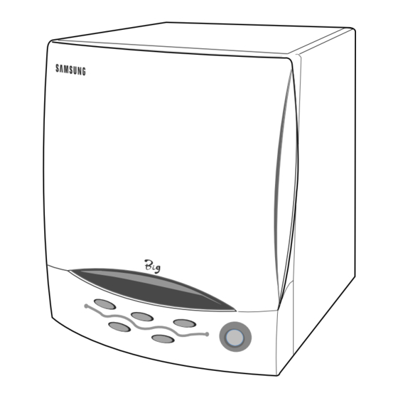
Summary of Contents for Samsung M308R
-
Page 1: Table Of Contents
MICROWAVE OVEN M308R (MELON / GRAY / YELLOW) SERVICE Manual MICROWAVE OVEN CONTENTS 1. Precaution 2. Specifications 3. Operating Instructions 4. Disassembly and Reassembly 5. Alignment and Adjustments 6. Troubleshooting 7. Exploded Views and Parts List 8. PCB Diagrams 9. Schematic Diagrams... - Page 2 (e) A Microwave leakage check to verify compliance with the Federal performance standard should be performed on each oven prior to release to the owner. Samsung Electronics...
-
Page 3: Precaution
10. Service technicians should remove their watches while repairing an MWO. 16. Always connect a test instrument's ground lead to the instrument chassis ground before connecting the positive lead; always remove the instrument's ground lead last. Samsung Electronics... - Page 4 (Use a screwdriver.) 3. High voltage is maintained within specified limits by close-tolerance, safety-related components and adjustments. If the high voltage exceeds the specified limits, check each of the special components. Samsung Electronics...
-
Page 5: Specifications
2-1 Table of Specifications TIMER 15 MINUTES POWER SOURCE 230V 50Hz, AC POWER CONSUMPTION MICROWAVE : 800W OUTPUT POWER 500W (IEC-705 TEST PROCEDURE) OPERATING FREQUENCY 2,450MHz MAGNETRON OM52S(20) COOLING METHOD COOLING FAN MOTOR OUTSIDE DIMENSIONS 281(W) x 330.5(H) x 316(D) Samsung Electronics... -
Page 6: Operating Instructions
3. Operating Instructions 3-1 Control Panel Convenience Features (Drinks, Snacks, Meals) Stop Button Time Feature 3-2 Features & External Views Glass Cook Tray Door latches Display Control Panel Door 316mm 281mm Samsung Electronics... -
Page 7: Disassembly And Reassembly
There exists HIGH VOLTAGE ELECTRICITY with high current capabilities in the circuits of the HIGH VOLTAGE TRANSFORMER secondary and filament terminals. It is extremely dangerous to work on or near these circuits with the oven energized. DO NOT measure the voltage in the high voltage circuit including filament voltage of magnetron. Samsung Electronics... -
Page 8: Replacement Of Door Assembly
2. When 15A fuse blows out by the operation of interlock monitor switch failure, replace the primary interlock switch, door sensing switch, monitor switch and power relay. 3. When the above three switches operate properly, check if any other part such as the control circuit board, blower motor or high voltage transformer is defective. Samsung Electronics... -
Page 9: Replacement Of Control Circuit Board
1. Window display should not be disassembled as its mounting tabs will be broken. If repair work is difficult, replace with Ass'y control panel. 2. The membrane key board is attached to the escutcheon base with doublefaced adhesive tape. Therefore, applying hot air such as using of hair dryer is recommended for smoother removal. Samsung Electronics... -
Page 10: Alignment And Adjustments
2. Isolate the magnetron from the circuit by disconnecting its leads. 3. A continuity check across the magnetron filament terminals should indicate one ohm or less. 4. A continuity check between each filament terminal and magnetron case should read open. Magnetron Antenna Cooling Fins Samsung Electronics... -
Page 11: High Voltage Capacitor
Door Closed ¥ 5. Confirm that the gap between the switch Primary switch ¥ Monitor switch (COM-NC) housing and the switch actuator is no more than ¥ Monitor switch (COM-NO) 0.5mm when door is closed. ¥ Door Sensing S/W Samsung Electronics... -
Page 12: Output Power Of Magnetron
5cm to any metal. If it gets closer than 5cm, erroneous readings may result. 5) Measured leakage must be less than 4mW/cm , after repair or adjustment. Maximum allowable leakage is 5mW/cm 4mW/cm is used to allow for measurement and meter accuracy Samsung Electronics... -
Page 13: Check For Microwave Leakage
; CENTRAL SERVICE CENTER 5-12-2 At least once a year have the microwave energy survey meter checked for accuracy by its manufacturer. Samsung Electronics... -
Page 14: Troubleshooting
H.V.Transformer component test procedure and replace if it is H.V.Capacitor defective. H.V.Diode, H.V.Fuse Magnetron 4. Open or loose wiring of power relay 5. Defective primary latch switch 6. Defective power relay or Ass'y PCB Replace PCB main. Samsung Electronics... - Page 15 Uneven intensity of microwave due to Wrap thinner parts of the food with its characteristics. aluminum foil. Use plastic wrap or cover with a lid. Stir once or twice while cooking foods such as soup, cocoa, or milk. Samsung Electronics...
-
Page 16: Exploded Views And Parts List
7. Exploded Views and Parts List 7-1 Exploded Views Samsung Electronics... -
Page 17: Main Parts List
PANEL-OUTER;SECC T0.5,W296.5,L931,-,MELON MELON DE70-10012B PANEL-OUTER;C/STEEL,T0.5,931,296.5,JE320GA GRAY DE70-10012L PANEL-OUTER;T0.5,W931,L296.5,EURO-YEL,M308R-Y YELLOW DE64-40313B DOOR-C;PP,-,BLK,-,JE320GA DE92-40212B ASSY DOOR;M308A,MELON-YEL(88099) MELON DE94-00007B ASSY DOOR;M308-D/AMF,DARK GREY GRAY DE94-00007E ASSY DOOR;M308R-Y/BWT,EURO-YEL YELLOW DE92-50131B ASSY DOOR-E;JE320GA,-,BLK,GE DE64-40329B DOOR-A;ABS-HR0370D,-,MELON-GRN(88099) MELON DE64-40329G DOOR-A;ABS(G3328),DARK-GRAY,M308-D/AMF GRAY DE64-40329J DOOR-A;ABS(HR0370),-,-,-,EURO-YEL,M308R-Y/BWT YELLOW DE64-40312B DOOR-KEY;POM(TC30005),10G,BLK,T0.2,-,-, DE61-70029A SPRING-KEY;ES,HSWR10,PI0.6,D6.0,L31.3,BLU DE92-90543A ASSY-COVER MGT;JE320,GE... -
Page 18: Standard Parts List
Parts No. Description/Specification Q'ty Remarks DE39-20145A ASSY POWER CORD;MOONSUNG,-,230V50Hz,-,-,-,M308 DE47-20173A THERMOSTAT;PW-2N(90/60)30,187Y,250V7.5A,9 DE93-20096B ASSY BODY LATCH;JE324,GE-EUROPE DE94-00008F ASSY CONTROL-BOX;230V50HZ,M308R-A/BWT,M/GREEN MELON DE94-00008E ASSY CONTROL-BOX;230V50HZ,M308R-D/BWT,DARK GRY GRAY DE94-00008J ASSY CONTROL-BOX;230V50HZ,M308R-Y/BWT,EURO-YEL YELLOW DE94-00006F ASSY CONTROL-PANEL;230V50HZ,M308R-A/BWT,M/GRN,88099 MELON DE94-00006E ASSY CONTROL-PANEL;230V50HZ,M308R-D/BWT,D/GRY,G3328 GRAY DE94-00006J ASSY CONTROL-PANEL;230V50HZ,M308R-Y/BWT,EURO-YELLOW YELLOW DE39-40754A WIRE HARNESS-A;230V50Hz,M308,EUROPE... - Page 19 8. P.C.B Diagrams 8-1 P.C.B Diagram Samsung Electronics...
- Page 20 Parts No. Description / Specification Q'ty Remarks 0703-001048 DISPLAY-LED;GRN,4digit,7seg,45.2x22.38x27. DSP1 1003-001033 IC-SOURCE DRIVER;TD62781AP,DIP,18P,300MIL,OCTAL IC02 3501-001062 RELAY-POWER;24VDC,523.2mW,16A,1FormA,15mS, RY01 3601-001126 FUSE-FERRULE;250V,1.6A,QUICK-ACTING,CERAMIC FUS1 DE09-00038A IC-MCU;KS57C0004-R1E,M308R,4BIT IC01 DE13-20016A IC-VOLT REGU;KA7805A,TO-220AB,1A,0/125C RG01 DE26-20146A TRANS-L.V;SLV-745EN,230V,50HZ,AC17/7V LVT1 DE30-20016A BUZZER;CBE2220BA,STICK BUZ1 DE39-40760A WIRE HARNESS;DC24V,M308/RE400,WIRE-FLAT,5P CN02 DE47-40024A HOLDER-FUSE;FH-51H,7.5A FUS1 0401-001025 DIODE-SWITCHING;1N4148M,50V,450mA,DO-34,TP...
-
Page 21: Schematic Diagrams
9. Schematic Diagrams 9-1 Schematic Diagram PRIMARY ASSY NOISE FILTER H.V.TRANS DIODE L. V .T CAPACITOR 230V FUSE 50Hz G/YEL MONITOR P.C.B FUSE PATTEN MAGNETRON THERMAL POWER RELAY KEY BOARD DOOR L. V. TRANS SENSING ASSY MAIN P. C. B Samsung Electronics...


