Sign In
Upload
Manuals
Brands
Motorola Manuals
Radio
GM140
Motorola GM140 Manuals
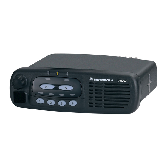
Manuals and User Guides for Motorola GM140. We have
4
Motorola GM140 manuals available for free PDF download: Basic Service Manual, Service Information
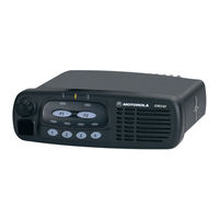
Motorola GM140 Basic Service Manual (46 pages)
Professional Radio
Brand:
Motorola
| Category:
Two-Way Radio
| Size: 1.45 MB
Table of Contents
Computer Software Copyrights
2
Safety Information
3
Operational Warnings
4
Potentially Explosive Atmospheres
4
Blasting Caps and Areas
4
Table of Contents
5
Chapter 1 INTRODUCTION
7
Scope of Manual
7
Warranty and Service Support
7
Warranty Period and Return Instructions
7
After Warranty Period
7
European Radio Support Centre (ERSC)
8
Piece Parts
8
Technical Support
9
Radio Model Information
10
Chapter 2 MODEL CHART and TEST SPECIFICATION
11
Model Chart (UHF 403-470 Mhz)
11
Model Chart (VHF 136-174 Mhz)
12
Model Chart (Low Band 29-50 Mhz)
13
Specifications
14
Chapter 3 MAINTENANCE
17
Introduction
17
Preventive Maintenance
17
Inspection
17
Cleaning Procedures
17
Safe Handling of CMOS and LDMOS Devices
18
Repair Procedures and Techniques - General
19
Disassembling and Reassembling the Radio - General
19
Radio Disassembly - Detailed
20
Control Head Removal
20
Top Cover Removal
21
Transceiver Board Removal
22
Disassembly of Control Head - GM340 (Without Display)
23
Disassembly of Control Heads - GM360 and GM380 (with Display)
24
Radio Assembly
25
Control Head - GM340
25
Control Heads - GM360 and GM380
25
Radio Chassis and Transceiver Board
26
Control Head Fitting
26
Radio Exploded Mechanical Views and Parts Lists
27
Radio Assembly - 25W Models
27
Radio Assembly - 60W Models
28
Control Head - GM340
29
Control Head - GM360
30
Control Head - GM380
31
Service Aids
32
Test Equipment
33
11.0 Programming/Test Cable - RKN4083
34
Chapter 4 TRANSCEIVER PERFORMANCE TESTING
35
General
35
Setup
35
RF Test Mode
36
Chapter 5 RADIO TUNING and PROGRAMMING
41
Introduction
41
CPS Programming Setup
41
Radio Tuning Setup
43
Initial Test Equipment Control Settings
43
Chapter 6 POWER up SELF-TEST
45
Error Codes
45
Advertisement
Motorola GM140 Service Information (32 pages)
GM Series Professional Radio
Brand:
Motorola
| Category:
Radio
| Size: 1.16 MB
Table of Contents
Computer Software Copyrights
2
Table of Contents
3
Chapter 1 MODEL OVERVIEW
5
GM140/GM340/GM640 Models
5
GM160/GM360/GM660 Models
5
GM380/GM1280 Models
6
Chapter 2 THEORY of OPERATION
7
Introduction
7
Controlhead Model for GM140, GM340 and GM640
7
Power Supplies
7
Power on / off
7
Microprocessor Circuit
7
SBEP Serial Interface
8
Keypad Keys
8
Status LED and Back Light Circuit
9
Microphone Connector Signals
9
Speaker
10
Electrostatic Transient Protection
10
Controlhead Model for GM160, GM360 and GM660
10
Power Supplies
10
Power on / off
10
Microprocessor Circuit
11
SBEP Serial Interface
11
Keypad Keys
12
Status LED and Back Light Circuit
12
Liquid Crystal Display (LCD)
12
Microphone Connector Signals
13
Speaker
14
Electrostatic Transient Protection
14
Controlhead Model for GM380 and GM1280
14
Power Supplies
14
Voltage Regulator Circuit
14
Power on / off
15
Microprocessor Circuit
15
SBEP Serial Interface
15
Keypad Keys
16
Status LED and Back Light Circuit
16
Liquid Crystal Display (LCD)
17
Microphone Connector Signals
17
Speaker
18
Electrostatic Transient Protection
18
Chapter 3 TROUBLESHOOTING CHARTS
19
On/Off
19
Microprocessor
20
Display
23
Backlight
24
On/Off
25
Microprocessor
26
Display
28
Keypad Backlight
29
Display Backlight
30
Chapter 4 CONTROLHEAD PCB/SCHEMATICS/PARTS LISTS
31
Allocation of Schematics and Circuit Boards
31
Motorola GM140 Service Information (34 pages)
GM Series Professional Radio VHF (136-174MHz)
Brand:
Motorola
| Category:
Radio
| Size: 0.11 MB
Table of Contents
Computer Software Copyrights
2
Table of Contents
3
Chapter 1 MODEL CHART and TECHNICAL SPECIFICATIONS
5
GM140/GM160 Model Chart
5
GM340/GM360/GM380 Model Chart
6
GM640/GM660/GM1280 Model Chart
7
Technical Specifications
8
Chapter 2 THEORY of OPERATION
11
Introduction
11
VHF (136-174Mhz) Receiver
11
Receiver Front-End
11
Front-End Band-Pass Filters & Pre-Amplifier
12
First Mixer and High Intermediate Frequency (IF)
12
Low Intermediate Frequency (IF) and Receiver Back End
12
VHF (136-174Mhz) Transmitter Power Amplifier (PA) 25 W
13
First Power Controlled Stage
13
Power Controlled Driver Stage
14
Final Stage
14
Directional Coupler
14
Antenna Switch
15
Harmonic Filter
15
Power Control
15
VHF (136-174Mhz) Frequency Synthesis
16
Reference Oscillator
16
Fractional-N Synthesizer
16
Voltage Controlled Oscillator (VCO)
17
Synthesizer Operation
18
VHF (136-174Mhz) Transmitter Power Amplifier (PA) 45 W
19
Power Controlled Stage
19
Pre-Driver Stage
20
Driver Stage
20
Final Stage
20
Directional Coupler
20
Antenna Switch
21
Harmonic Filter
21
Power Control
21
Chapter 3 TROUBLESHOOTING CHARTS
23
Troubleshooting Flow Chart for Receiver (Sheet 1 of 2)
23
Troubleshooting Flow Chart for Receiver (Sheet 2 of 2)
24
Troubleshooting Flow Chart for 25W Transmitter (Sheet 1 of 3)
25
Troubleshooting Flow Chart for 25W Transmitter (Sheet 2 of 3)
26
Troubleshooting Flow Chart for 25W Transmitter (Sheet 3 of 3)
27
Troubleshooting Flow Chart for 45W Transmitter (Sheet 1 of 2)
28
Troubleshooting Flow Chart for 45W Transmitter (Sheet 2 of 2)
28
Troubleshooting Flow Chart for Synthesizer
30
Troubleshooting Flow Chart for VCO
31
Chapter 4 VHF PCB/SCHEMATICS/PARTS LISTS
33
Allocation of Schematics and Circuit Boards
33
Controller Circuits
33
Advertisement
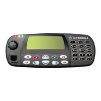
Motorola GM140 Service Information (32 pages)
GM series Professional Radio UHF (403-470MHz)
Brand:
Motorola
| Category:
Radio
| Size: 0.24 MB
Table of Contents
Computer Software Copyrights
2
Table of Contents
3
Chapter 1 MODEL CHART and TECHNICAL SPECIFICATIONS
5
GM140/GM160 Model Chart
5
GM340/GM360/GM380 Model Chart
6
GM640/GM660/GM1280 Model Chart
7
Technical Specifications
8
Chapter 2 THEORY of OPERATION
11
Introduction
11
UHF (403-470Mhz) Receiver
11
Receiver Front-End
11
Front-End Band-Pass Filters & Pre-Amplifier
12
First Mixer and High Intermediate Frequency (IF)
12
Low Intermediate Frequency (IF) and Receiver Back End
12
UHF (403-470Mhz) Transmitter Power Amplifier (PA) 25 W
13
First Power Controlled Stage
13
Power Controlled Driver Stage
14
Final Stage
14
Directional Coupler
14
Antenna Switch
15
Harmonic Filter
15
Power Control
15
UHF (403-470Mhz) Frequency Synthesis
16
Reference Oscillator
16
Fractional-N Synthesizer
16
Voltage Controlled Oscillator (VCO)
17
Synthesizer Operation
18
Power Controlled Stage
19
Pre-Driver Stage
19
Driver Stage
20
Final Stage
20
Directional Coupler
20
Antenna Switch
20
Harmonic Filter
20
Power Control
21
Troubleshooting Flow Chart for Receiver (Sheet 1 of 2)
23
Troubleshooting Flow Chart for Receiver (Sheet 2 of 2)
24
Troubleshooting Flow Chart for 25W Transmitter (Sheet 1 of 3)
25
Troubleshooting Flow Chart for 25W Transmitter (Sheet 2 of 3)
26
Troubleshooting Flow Chart for 25W Transmitter (Sheet 3 of 3)
27
Chapter 3 Troubleshooting Charts
28
Troubleshooting Flow Chart for Synthesizer
29
Troubleshooting Flow Chart for VCO
30
Troubleshooting Flow Chart for 40W Transmitter
28
Chapter 4 UHF PCB/SCHEMATICS/PARTS LISTS
31
Allocation of Schematics and Circuit Boards
31
Advertisement
Related Products
Motorola GM1280
Motorola GM1200E
Motorola GM1200 Series
Motorola GM160
Motorola GM100
Motorola GM398
Motorola GM350
Motorola GM660
Motorola GM300 Series
Motorola GM600
Motorola Categories
Cell Phone
Two-Way Radio
Baby Monitor
Cordless Telephone
Radio
More Motorola Manuals
Login
Sign In
OR
Sign in with Facebook
Sign in with Google
Upload manual
Upload from disk
Upload from URL