Sign In
Upload
Manuals
Brands
Kenwood Manuals
Transceiver
SP-990
Kenwood SP-990 Manuals
Manuals and User Guides for Kenwood SP-990. We have
2
Kenwood SP-990 manuals available for free PDF download: Service Manual, Instruction Manual
Kenwood SP-990 Service Manual (245 pages)
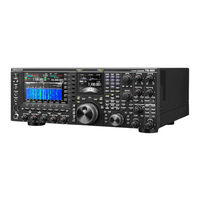
HF/50MHz TRANSCEIVER & EXTERNAL SPEAKER
Brand:
Kenwood
| Category:
Transceiver
| Size: 8.27 MB
Table of Contents
Controls and Knobs
1
Table of Contents
2
Safety Check after Repairs
2
Disassembly for Repair
3
Cautions for Reassembling the Main Knob ASSY
3
Forming the Two Coaxial Cables
3
Frequency Configuration
4
Reference Signal Generator
4
Main Receiver Block
4
Circuit Description
4
Mlo1/Mlo2
5
Reference Signal Generator of the Main Receiver Block, MLO1/MLO2
5
Transmission and Sub Receiver Blocks
6
MLO1/MLO2 Frequency Shift Data
6
Tlo1/Slo1/Slo2/Slo3
7
Frequency Confi Guration of the Transmission and Sub Receiver Blocks
7
Reference Signal Generator of the Transmitter and Receiver Block
8
SLO1/SLO3 Frequency Shift Data
9
Mode, Conversion Method, and if Frequency
10
From the Antenna Terminal to the Preselector Amplifier
10
Front Part of the Main Receiver Circuit
10
Main Receiver Circuit
10
From the Preselector Amplifier to the 1St if Frequency
11
From the 2Nd if to the MRIF Output
12
Preselector Circuit
12
Selecting an if Fi Lter
12
Preselector Operation Frequency
12
Preamplifier 1 Circuit
13
Configuration of the Preamplifier
13
Preamplifier Circuit
13
1St Mixer
14
Noise Blanker Filter and if Filter Adjustments
14
Preamplifier 2 Circuit
14
Preamplifier Key Display
14
IF Filter
15
Noise Blanker Filter and if Filter Adjustments
15
IF Filter Specifications
15
RX if Filter Settings
16
Noise Detection Circuit
17
Noise Detector
17
Noise Blanking Circuit
17
Noise Blanker Circuit
17
Sub Receiver Circuit
18
From the Antenna Terminal to the Sub Preamplifier
18
From the Sub Preamplifier to the 2Nd if
19
Frequency
19
BPF Range
19
Selecting the if Filter
20
Criteria for Selecting the SRX-1 Path or SRX-2 Path
20
2Nd if Frequency
20
From the 2Nd if to the SRIF Output
21
1St Mixer of the SRX-1 Path
21
MCF Adjustment
22
1St Mixer of the SRX-2 Path
22
The MCF Circuit of the SRX-1/2 Path
22
Noise Detector Circuit
24
Transmission Circuit
25
From the Transmission Signal to the Drive Output
25
Blanking Circuit
25
From the Drive Output to the Antenna Terminal
26
Antenna Tuner and Various Protections
26
Antenna Distribution Diagram
27
Scope Circuit
28
Transmit Power Control
28
From the if Input Stage to the if Amplifier
28
From the 2Nd Mixer to the 3Rd Mixer
28
Scref
29
PLL to SCLO1/SCLO2
29
From the 3Rd Mixer to the SCIF
29
From the if Amplifier to the 3Rd Mixer Output
29
DC/DC Converter Circuit
30
Interface Circuit
30
13.8 V Power Supply and 5 V Backup Power Supply
30
DSP Unit
31
14S, 5 V, and 33S Power Supplies
31
1.8V and 1.2V Power Supplies
31
Outline
31
Flow of Audio Clock
32
Reception Signal Path
32
Dsps and the Peripheral Circuit
32
Receive Signal Path
33
Transmission Signal Path
33
Signal Path to External I/O
34
Signal Paths of Recording Sound and Playback Sound
34
External I/O and Signal Paths of Recording and Playback Sounds
34
AGC Voltage Output Circuit
35
Main/Scope MCU and Its Periphery
35
Signal Path for the Band Scope and Decoder Use
35
Control Circuit
35
Scope DSP and Its Periphery
36
Scope if Signal
36
MSCPI Signal
36
SSCPI Signal
36
Digital Control Circuit
37
Application MCU and Its Periphery
37
Communication with the Main/Panel MCU
37
LAN Interface Circuit
37
Recording/Playback
38
USB Interface (Host)
38
DVI Output
38
Display Circuit
38
Accessory Unit
40
Components Description
40
DC-DC Unit
41
Final Unit
42
Digital Unit
43
PLL Unit
44
AT Unit
48
Control Unit
50
Display Unit
51
RX Unit
52
TX-RX Unit
55
Main MCU
60
Semiconductor Data
60
Scope-Sub MCU
61
Scope DSP
62
Extension Port IC
64
DSP-Sub MCU
67
Txmrx-Dsp
68
Srx-Dsp
70
Panel MCU
73
Parts List
75
Exploded View (Main Body Upper Side)
150
Main Body Lower Side
151
Panel
152
Wiring - Upper Side
154
Wiring - Lower Side
155
Wiring - Panel
156
Packing
157
Fault Diagnosis of the BGA (Ball Grid Array) IC
158
Trouble Shooting
158
Replacing Digital Unit
159
Updating Firmware
160
Required Test Equipment
160
Preparation
160
Adjustment
160
Jig Cable
161
ACC 2 Connector Short Plug
161
Adjustment Rod
161
Service Jig
161
Adjustment Mode
162
Operating Procedure for Adjustment Mode
162
Adjustment Mode Menu
163
Display Check
165
PLL Section
165
Receiver Section
168
Transmitter Section
195
Adjustment Points (Upper Side)
206
Lower Side
207
Accessory Units
210
Terminal Function
210
Main/Sub Band
238
Level Diagram
238
ARCP-990 (Radio Control Program)
240
ARHP-990 (Radio Host Program)
240
External Speaker
240
Schematic Diagram
241
Optional Accessories
240
Specifications
242
Advertisement
Kenwood SP-990 Instruction Manual (2 pages)
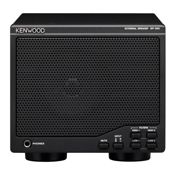
EXTERNAL SPEAKER
Brand:
Kenwood
| Category:
Speakers
| Size: 0.32 MB
Table of Contents
Supplied Accessories
1
Specifications
1
Panel Descriptions
2
Front Panel
2
Rear Panel
2
Advertisement
Related Products
Kenwood SP-930
Kenwood SP-120
Kenwood SP-180
Kenwood Trio SP-520
Kenwood SP-71
Kenwood SP-430
Kenwood SP-S30
Kenwood S-811B
Kenwood S0-1
Kenwood SO-1
Kenwood Categories
Car Receiver
Transceiver
CD Player
Amplifier
Receiver
More Kenwood Manuals
Login
Sign In
OR
Sign in with Facebook
Sign in with Google
Upload manual
Upload from disk
Upload from URL