Sign In
Upload
Manuals
Brands
Huawei Manuals
Accessories
V100R010
Huawei V100R010 Router Switch Manuals
Manuals and User Guides for Huawei V100R010 Router Switch. We have
2
Huawei V100R010 Router Switch manuals available for free PDF download: Quick Installation Manual, User Manual
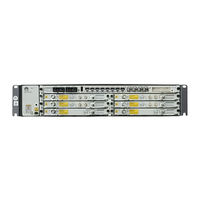
Huawei V100R010 Quick Installation Manual (50 pages)
Radio Transmission System
Brand:
Huawei
| Category:
Network Hardware
| Size: 19.69 MB
Table of Contents
Installation Process
3
Commissioning Process
4
Precautions
5
Electrostatic Discharge
5
Power Supply
5
Binding Cables
5
Instructions and Precautions for Handling Boards
6
Instructions and Precautions for Handling Power Cable Terminals
7
Precautions for Handling the Toggle Lever Switch
8
Position and Description of the Toggle Lever Switch
8
Turning on the Switch
8
Turning off the Switch
8
Precautions for Handling IDU-Side if Cables
9
Precautions for Handling ODU-Side if Cables
9
Precautions for Installing if Cables (Dual-Channel if Board)
10
Precautions for Removing if Cables
10
Precautions for Handling if Boards
11
Tools for Installation
12
Introduction to the RTN 950A Equipment
13
Ports
13
Installation Holes on both Sides of the Chassis
13
Installing the RTN 950A
14
Installing the Chassis in the 19-Inch Cabinet
14
Fixing Floating Nuts
14
Removing Screws
14
Installing the Chassis in the Cabinet
15
Installing PGND Cables
15
Installing the Chassis in the ETSI Cabinet
15
Installing the Chassis in the 23-Inch Cabinet
16
Wall-Mounting the Chassis
17
Removing Mounting Ears
17
Marking and Drilling Holes
17
Desk-Mounting the Chassis
20
Installing Plastic Feet
20
Optional: Installing the E1 Panel
20
Fixing the E1 Panel
21
Installing PGND Cables on the E1 Panel
21
Optional: Installing Transfer Brackets for if Jumpers
22
Installing if Connectors
22
Installing Two if Connectors
22
Installing Transfer Brackets for if Jumpers
23
Installing Transfer Brackets for if Jumpers in 19-Inch Cabinets
23
Installing Transfer Brackets for if Jumpers in ETSI Cabinets
23
Installing Transfer Brackets for if Jumpers on Walls
24
Installing Boards
25
Installing IDU Cables
25
Installing Power Cables
26
Installing E1 Cables
27
Optional: Connecting E1 Cables to the External Equipment
27
Optional: Connecting E1 Cables to the E1 Panel
28
Optional: Connecting E1 Cables to the TCU6 Board
28
Installing Ethernet Service Cables
29
Installing XPIC Cables
29
Installing if Jumpers
30
Optional: Connecting the if Jumper Directly to the if Cable
30
Installation Effectiveness in the 19-Inch Cabinet
31
Installation Effectiveness in the ETSI Cabinet
31
Installation Effectiveness on the Wall
32
Installing Fibers
33
Installing STM-1E Cables
34
Installing NM Cables
34
Installing NM Cables (for a Gateway NE)
34
Installing Orderwire Phone Cables
35
Installing External Clock Cables
36
Assembling External Clock Cables Based on the Pin Assignment
36
Installing External Clock/Time Cables for the IDU
36
Installing Asynchronous and Synchronous Data Cables
37
Installing Synchronous and Asynchronous Data Cables for the IDU
37
Installing External Alarm Cables
38
Installing External Alarm Cables for the IDU
38
Cable Layout Effectiveness
39
Cable Connections
39
Powering on the Equipment
40
Status Description of Indicators
40
Configuring NE Data (Using the USB Flash Drive)
41
Insert a USB Flash Drive
41
Configuring NE Data (by Using the Web LCT)
42
Configuring NE Data (by Using the Hand-Held Tool)
42
Aligning Antennas
43
Aligning Single-Polarized Antennas
43
Aligning Dual-Polarized Antennas
44
Checking the Radio Link Status
45
Checking the Installation
46
Connecting Cables to a Power Cable Connector
47
Obtaining Tools, Cables, and a Power Cable Connector
47
Peeling Cables
47
Connecting Cables to the Power Cable Connector
48
Advertisement
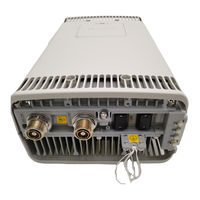
Huawei V100R010 User Manual (46 pages)
Brand:
Huawei
| Category:
Accessories
| Size: 1.01 MB
Table of Contents
Table of Contents
3
About this Document
9
1 Changes in the RRU3804 User Guide
13
2 DBS3900 Hardware Configuration
15
Typical Configurations of the DBS3900
16
Table 2-1 Typical Configurations of the DBS3900
16
Figure 2-1 Cable Connections of the DBS3900 in Type 3 X 1 Configuration
17
4-Way RX Diversity Configuration
18
Figure 2-2 Cable Connections of the DBS3900 in Type 3 X 4 Configuration
18
Table 2-2 Number of Modules in the DBS3900 in 4-Way RX Diversity Configuration
19
TX Diversity Configuration
20
Figure 2-3 Cable Connections of the DBS3900 in 4-Way RX Diversity Configuration
20
Table 2-3 Number of Modules in the DBS3900 in TX Diversity Configuration
21
X 2 MIMO Configuration
22
Figure 2-4 Cable Connections of the DBS3900 in TX Diversity Configuration
22
Table 2-4 Number of Modules in the DBS3900 in 2 X 2 MIMO Configuration
23
Figure 2-5 Cable Connections of the DBS3900 in 2 X 2 MIMO Configuration
24
3 RRU Hardware
25
RRU Equipment
26
Appearance of the RRU3804
26
Figure 3-1 Appearance of the RRU3804
26
Panels of the RRU3804
27
Figure 3-2 Panels of the RRU3804
27
Leds on the RRU3804
28
Table 3-1 Ports and Leds on the Panels of the RRU3804
28
Table 3-2 Leds on the RRU3804
28
RRU Cables
29
RRU3804 Cable List
30
Table 3-3 RRU3804 Cable List
30
PGND Cable of the RRU
31
Figure 3-3 PGND Cable
31
Power Cable of the RRU
32
Figure 3-4 2-Hole Terminal
32
Figure 3-5 -48 V DC Power Cable
32
Table 3-4 Pin Assignment for the Wires of the -48 V DC Power Cable (North American Standard)
32
CPRI Optical Cable
33
Figure 3-6 CPRI Optical Cable
33
Table 3-5 Pin Assignment for the Wires of the -48 V DC Power Cable (European Standard)
33
AISG Multi-Wire Cable of the RRU
34
Figure 3-7 AISG Multi-Wire Cable
34
Table 3-7 Pin Assignment for the Fiber Tails of the CPRI Optical Cable between Rrus
34
AISG Extension Cable of the RRU
35
Figure 3-8 AISG Extension Cable
35
Table 3-8 Pin Assignment for the Wires of the AISG Multi-Wire Cable
35
RF Jumper of the RRU
36
Figure 3-9 Antenna Jumper
36
Table 3-9 Pin Assignment for the Wires of the AISG Extension Cable
36
Figure 3-10 Interconnect Jumper
37
Table 3-10 RF Jumper Connections of the RRU
37
Alarm Cable of the RRU
38
Figure 3-11 Alarm Cable
39
Table 3-11 Pin Assignment for the Wires of the Alarm Cable
39
4 Maintaining the Hardware of the RRU
41
Maintenance Items of the RRU
42
Powering on and Powering off the RRU
42
Powering on the RRU
42
Table 4-1 Maintenance Items of the RRU
42
Powering off the RRU
43
Replacing the RRU
44
Replacing an Optical Module
45
Figure 4-1 Removing an RRU
45
Advertisement
Related Products
Huawei V100R009
Huawei V100R008C01
Huawei V200R010
Huawei V200R011
Huawei V300R008
Huawei 9000 VCT V100R011
Huawei V100R017
Huawei V100R012
Huawei V100R013C00
Huawei 3900 Series
Huawei Categories
Cell Phone
Network Router
Wireless Router
Modem
Inverter
More Huawei Manuals
Login
Sign In
OR
Sign in with Facebook
Sign in with Google
Upload manual
Upload from disk
Upload from URL