Sign In
Upload
Manuals
Brands
Hitachi Manuals
Air Conditioner
FXG1 Series
Hitachi FXG1 Series Manuals
Manuals and User Guides for Hitachi FXG1 Series. We have
1
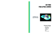
Hitachi FXG1 Series manual available for free PDF download: Technical Catalogue
Hitachi FXG1 Series Technical Catalogue (424 pages)
Set-free outdoor and indoor units
Brand:
Hitachi
| Category:
Air Conditioner
| Size: 22.86 MB
Table of Contents
Table of Contents
6
1 System Description
15
Features and Benefits
16
System Description
17
Features on Indoor Units and Outdoor Units
22
RCI - Four Way Cassette Type
22
RCD - Two-Way Cassette Type
23
RPC - Ceiling Type
23
RPI - In-The-Ceiling Type
24
RPF - Floor Type
25
RPFI - Floor Concealed Type
25
RPK - Wall Type
25
Slim and Compact Outdoor Unit
26
Name of Parts
27
Indoor Units
27
Outoor Units
31
2 General Data
35
General Data
36
RCI - 4-Way-Cassette Type
36
RCD - 2-Way-Cassette Type
37
RPC - Ceiling Type
38
RPI - In-The-Ceilingtype (0.8 ~ 1.5HP)
39
RPI - In-The_Ceiling Type (2.0 ~ 5.0HP)
40
RPK - Wall Type
41
RPF & RPFI - Floor & Floor Concealed Type
42
General Data for Indoor Units
36
General Data for Outdoors Units
43
RAS - Outdoors Unit (FSG/FSG1)
43
RAS - Outdoors Unit (FXG/FXG1)
44
Component Data
45
RCI - 4-Way Cassette Type
45
RCD - 2-Way Cassette Type
45
RPC - Ceiling Type
46
RPI - In-The-Ceiling Type
46
RPF - Floor Type and RPFI - Floor Concealed Type
47
RPK - Wall Type
47
Compressor
48
Outdoor Heat Exchanger and Fan (FSG/FSG1)
48
Outdoor Heat Exchanger and Fan (FXG/FXG1)
48
3 Dimensional Data
49
Indoor Units
50
Dimensional Data
50
4-Way Cassette Type Models: RCI-1.0 with Air Panel P-G12WA(H)2E
50
RCI-1.5~3.0 with Air Panel P-G23WA(H)2E(1)
50
4-Way Cassette Type Models: RCI-4.0/5.0 with Air Panel P-G46WA(H)2E(1)
51
2-Way Cassette Type Models: RCD-1.0~3.0 with Air Panel P-G23DWA1
52
2-Way Cassette Type Models: RCD-4.0/5.0 with Air Panel P-G46DWA1
53
Ceiling Type Models: RPC-2.0
54
Ceiling Type Models: RPC-2.5/3.0
55
Ceiling Type Models: RPC-4.0
56
Ceiling Type Models: RPC-5.0
57
In -The-Ceiling Type Models: RPI-0.8~1.5
58
In-The-Ceiling Type Models: RPI-2.0~3.0
59
In-The-Ceiling Type Models: RPI-4.0/5.0
60
Way Type Models: RPK-1.0~2.3
61
Floor Type Models: RPF-1.0~2.5
62
Floor Type Models: RPFI-1.0~2.5
63
Model: CH Unit (CH-4.0/6.5GE)
64
Model: CH Unit (CH-11.5G)
65
Outdoor Units
66
Model: RAS-5FSG
66
Models: RAS-8/10FSG
67
Models: RAS-16/20FSG
68
Model: RAS 24/30-FSG1
69
Models: RAS-8/10FXG
70
Model: RAS-20FXG1
71
Model: RAS-30FXG1
72
4 Capacities and Selection Data
73
System Selection Procedure
74
Capacities and Selection Data
74
Selection Guide
74
Operation Space
77
RCD 2-Way Cassette Type
77
RCI 4-Way Cassette Type
77
RPC Ceiling Type
78
RPF Floor Type
78
RPI In-The-Ceiling Type
78
RPK Wall Type
78
Outdoor Units
79
RPFI Floor Concealed Type
79
Capacity Characteristic Curves of Outdoor Units
80
Cooling Capacity Table of 100% Combination
83
Heating Capacity Table of 100% Combination
84
Correction Factor According to Piping Length
86
Sensible Heat Factor (SHF)
88
Correction Factor for Defrosting Operation
89
Fan Performance
89
Temperature Distribution Diagrams
91
RCI 4-Way Cassette Type
91
RCD 2-Way Cassette Type
93
RPC-Ceiling Type
95
Sound Data
96
RCI - 4- Way Cassette Type
96
RCD - 2-Way Cassette Type
98
RPC - Ceiling Type
100
RPI - In-The-Ceiling Type
102
RPK - Wall Type
104
RPF - Floor Type
105
RPFI - Floor Concealed Type
106
RAS - Outdoor Units FSG
107
RAS- Outdoor Units FSG1
108
RAS- Outdoor Units FXG
109
5 Working Range
111
Power Supply
112
6 Electrical Data
113
Indoor Unit
114
Outdoor Unit
115
7 Electrical Wiring Diagrams
117
ELECTRICAL WIRING DIAGRAM (for Models: RCI-1.0 ~ 5.0)
121
ELECTRICAL WIRING DIAGRAM (for Models: RCD-1.0 ~ 3.0)
123
ELECTRICAL WIRING DIAGRAM (for Models: RCD-4.0 ~ 5.0)
125
ELECTRICAL WIRING DIAGRAM (for Models: RPC-2.0 ~ 5.0)
127
ELECTRICAL WIRING DIAGRAM (for Models: RPI-0.8 ~ 1.5)
129
ELECTRICAL WIRING DIAGRAM (for Models: RPI-2.0 ~ 5.0)
131
ELECTRICAL WIRING DIAGRAM (for Models: RAS-5FSG)
133
ELECTRICAL WIRING DIAGRAM (for Models: RPK-1.0 ~ 2.3)
133
ELECTRICAL WIRING DIAGRAM (for Models: RAS-8FSG, RAS-10FSG)
134
8 Refrigerant Cycle
135
Outdoor Units
136
Refrigerant Cycle
136
Ras-5Fsg
136
Ras-8/10Fsg
137
Ras-16/20Fsg
138
Ras-24/30Fsg1
139
Ras-8/10Fxg
140
Ras-20Fxg1
141
Ras-30Fxg1
142
CH - Units
143
CH Unit CH-4.0GE
143
CH Unit CH-6.5GE
144
CH Unit CH-11.5G
145
9. Control System
147
9 Control System
147
Control System
148
20Fsg
148
Ras-24/30Fsg1
149
Ras-8/10Fxg
150
Ras-20/30Fxg1
151
Device Control System
148
Indoor Unit PCB
152
Printed Circuit Board Layout (Except RPK)
152
Printed Circuit Board Layout (Only RPK)
153
Dip Switch Setting
154
Outdoor Unit PCB
155
Printed Circuit Board Layout
155
Dip Switch Setting
156
Protection and Safety Control
158
Safety and Control Device Setting
158
Standard Operation Sequence
159
Cooling Operation (FSG, FSG1)
159
Cooling (Mainly Cooling) Operation (FXG, FXG1)
161
Dry Operation (FSG, FSG1)
163
Dry Operation (FXG, FXG1)
165
Heating Operation (FSG, FSG1)
167
Heating (Mainly Heating) Operation (FXG, FXG1)
169
Standard Control Functions
172
Freezing Protection Control During Cooling or Dry Operation
172
Gas Bypass Control
173
Over Heating Protection Control
173
Control of Expansion Valve for Plate Heat Exchange
174
Compressor Running Control
175
Control for Auto Cool/Heat Operation
176
10 Available Optional Functions
177
Available Optional Functions
178
Input and Output Setting of Indoor PCB Connector
178
Remote Control ON/OFF Function
180
Control by Field-Supplied Room Thermostat
182
Remote Temperature Sensor Control
182
Picking up Signals
183
Indoor Unit (Except RPK)
178
Indoor Unit (RPK Only)
184
Remote ON/OFF Operation (1/2)
184
Cancellation of Commands from RCS after Forced Stoppage (3)
186
Remote Cooling / Heating Mode Change over (4)
186
Automatic Operation When Power Supply on (5)
187
Control by Field Supplied Room Thermostat (7)
187
Picking up Signals
187
Restarting Function after Power Failure (6)
187
Outdoor Units
188
Input and Output Settings of Outdoor Unit Connector
188
Demand (3)
190
Enforced Stoppage (5)
190
Snow Sensor
190
Defrosting Condition Changeover
191
Demand Current Control (Only for 24 and 30 HP) (6/7/8)
191
Indoor Fan Control During Thermo-OFF at Heating
191
All Season Cooling Operation
192
All Season Heating Operation
192
Night Shift (Low Sound) Operation
193
Picking up Signals from Outdoor Unit Printed Circuit Board
194
Optional Functions Available through Remote Control Switch
195
Optional Functions Setting
195
Optional Functions of Remote Control Switch
198
Optional Functions Available through Remote Control Switch (PC-P5H)
201
Optional Functions Available through Wireless Remote Control Switch (PC-LH3 + Receiver)
202
Optional Functions Available through Wireless Remote Control Switch (PC-LH3A + Receiver)
202
Optional Functions
202
Setting of Sub-Receiver Part
202
11 Remote Controllers Operation
203
Remote Controllers Operation
204
Operation Procedure for Cooling, Heating, Dry and Fan Operations
205
Operation Procedure for Temperature, Fan Speed and Air Louver Direction Setting
205
Operation Procedure for Timer Operation
206
Operation Procedure for Ventilation
206
Operation Procedure for Automatic Cooling/Heating Operation
206
Operation Procedure for Swing Louver Adjustment
207
Indication When in Normal Condition
208
Indications When in Abnormal Condition
208
Optional Remote Controller (PC-5H)
209
Liquid Crystal Remote Control Switch (PC-P1HE)
204
Optional Remote Controller (PC-P5H)
209
Optional Wireless Remote Control Switch, PC-LH3A
210
Operation Procedure
211
Air Panel Wireless Control
212
Receiver Kit
212
Operation for Multiple Indoor Units
213
Optional 7-Day Timer (PSC-5T)
215
Setting Present Day and Present Time
216
Changing Weekly Schedule Pattern (a or B)
216
Setting On/Off Time
217
Setting Holiday
218
Setting Running Day
218
Checking Contents of Setting
219
Optional Central Station (PSC-5S)
220
Group Selection and Monitoring Unit Operation Status
221
Setting of Operation Mode
222
Setting of Temperature, Fan Speed and Louver Angle
222
Prohibiting Operation by Remote Control Switch
224
Unit Operation
224
Other LDC Indications
225
Timer Operation
225
Optional Accessories for RCS
226
Indication in Abnormal Conditions
226
Remote Control Cable (PRC-10E1~PRC-30E1)
226
Connector Cable
227
Remote Control Cable (PRC-10E~PRC-30E)
227
12 Units Installation
231
Transportation and Handling
233
Units Installation
233
Transportation of Outdoor Unit
233
Factory-Supplied Accessories
233
RCI (4-Way Cassette Type)
234
Initial Check
234
Installation
235
Air Panels for Installation
236
RCD (2-Way Cassette Type)
238
Factory-Supplied Accessories
238
Initial Check
238
Installation
239
Opening of False Ceiling and Suspension Bolt
239
Air Panels for Installation
240
RPC (Ceiling Type)
242
Factory Supplied Accessories
242
Initial Check
242
Installation
242
RPI (In-The-Ceiling)
245
Initial Check
245
Installation
245
Air Suction Direction Change
246
Connecting Supply Duct
246
Fix Flexible Duct to External Faces of Flanges
246
RPK (Wall Type)
247
Factory-Supplied Accessories
247
Initial Check
247
Installation
247
RPF (Floor Type) / RPFI (Floor Concealed Type)
249
Factory-Supplied Accessories
249
Initial Check
249
Installation
249
RAS (Outdoor Unit)
251
Installation Location (5 to 10 HP)
251
Installation Space for Single Unit
251
Serial Units Installation
252
Multiple Installation Space
254
Foundation Provision
260
Dimensions of the Hood (Field-Supplied)
262
Transportation and Installation of CH Unit
269
Transportation and Handling
269
Installation
269
Optional Accessories
272
Remote Sensor (THM-R2E)
272
Fresh Air Intake for 4-Way Cassette Type Indoor Units
272
Branch Discharge Duct for 4-Way Cassette Type Indoor Units
273
Direction Air Flow for 4-Way Cassette Type Indoor Units
275
Outdoor Unit Drain-Kit (DBS-26)
276
13 Refrigerant Piping and Refrigerant Charge
277
Refrigerant Piping Selection
278
Refrigerant Piping and Refrigerant Charge
278
Refrigerant Piping Work Range
278
Refrigerant Piping Length
280
Piping Size and Multi-Kit FSG/FSG1
283
Distributor Line Branch and Header Branch
286
Dimensional Data
286
Distribution Method
293
Piping Work Connection Considerations
295
Piping Materials
295
Three Principles on Refrigerant Piping Work
297
Indoor Unit Piping Work Connection
300
Way Cassette Type
300
RPC - Ceiling Type
300
RPI - In-The-Ceiling Type
301
RPK - Wall Type
302
CH Unit
303
RPF & RPFI - Floor Type & Floor Concealed Type
303
Outdoor Unit Piping Work Connection
304
Factory Supplied Pipe Accessories
304
Position of Piping Connection
304
Flange Piping Connection
306
Piping Connection
307
Installing Dryer in Liquid Line
308
Refrigerant Charging Quantity
310
Guide of Additional Refrigerant Charge Calculation (R407C)
310
Samples
312
Vacuum and Refrigerant Charge
322
Caution on Refrigerant Leakage
323
Maximum Permissible Concentration of HCFC Gas
323
Calculation of Refrigerant Concentration
323
Countermeasure for Refrigerant Leakage According to KHK Standard
323
14 Drain Piping
325
Drain Piping
326
General
326
14 Drain Piping
327
RCI (4-Way Cassette Type)
327
RCD (2-Way Cassette Type)
327
RPC (Ceiling Type)
328
RPI (In-The-Ceiling Type)
329
RPK (Wall Type)
330
RPF and RPFI (Floor Type and Floor Concealed Type)
330
Outdoor Unit Drain-Kit (DSB-26)
330
Outdoor Unit Drain-Kit (DBS-26)
330
15 Electrical Wiring
331
Electrical Wiring
332
General Check
332
Electrical Wiring for Outdoor Units
332
Electrical Wiring for Outdoor Unit
332
Electrical Wiring Connection
332
Electrical Wiring for Indoor Units
334
RCI Units
334
RCD Units
335
RPC Units
335
RPI Units
336
RPK Units
336
RPF/RPFI Units
337
Setting of DIP Switches for Indoor Unit
338
Common Wiring
339
Electrical Wiring between Indoor Unit and Outdoor Unit
339
H-LINK System
341
Wire Sizes
343
16 Installation of Optional Remote Controller
345
Installation of Remote Control Switch <PC-P1HE
347
Before Installation
347
Installation Space
347
Installation Procedure
348
Electrical Wiring
349
Installation of Optional Remote Controller
347
Installation of Remote Control Switch (Core-Function) <PC-P5H
350
Electrical Wiring
351
16 Installation of
350
Installation of Central Station <PSC-5S
353
Accessories
353
Installation Procedure
353
Installation Space
353
Input/Output Function
358
Option Setting
360
Initialization of Central Station
361
Installation of 7-Day Timer <PSC-5T
362
Accessories
362
Installation Space
362
Installation Procedure
362
Electrical Wiring
364
Psc-5S
365
Dip Switches Setting
365
Installation of Receiver Kit <PC-RLH4
366
Pc-Rlh4
366
Installation of Wireless Receiver Kit
366
Installation of Receiver Kit
368
Pc-Rlh9
368
Installation of Receiver Kit <PC-RLH9
368
Installation of Wireless Receiver Kit
368
Installation of Receiver Kit <PC-RLH11
369
Installation of Wireless Receiver Kit
369
Pc-Rlh11
369
Harc
371
Name of Parts
371
Installation Procedure
371
Arrangement of the Installation of PCB and H-LINK Terminals
373
Electrical Wiring
373
Maintenance and Service
373
Fsg - Fxg - G7 - Hrg - Usb/H-Link Connection
374
17 Test Run
377
Checking before Test Run
378
Test Run
378
Test Run Procedure by Remote Control Switch
379
Test Run Procedure by WIRELESS Remote Control Switch (PC-LH3A)
380
Test Run from Outdoor Unit Side
383
Checking of the Refrigerant Quantity
386
Checking of Refrigerant Quantity
386
FSG System
386
FXG System
390
18 Troubleshooting
393
Initial Troubleshooting
394
Not Cooling or Heating Well
394
Not Operate
394
This Is Not Abnormal
394
Troubleshooting
394
Alarm Codes
395
Troubleshooting in Check Mode
396
Troubleshooting by 7-Segment Display
402
Checking Method by 7-Segment Display
402
Simple Checking by 7-Segment Display
402
Protection Control Code on 7-Segment Display
408
Self Checking of Pcb's Using Remote Control Switch
411
Self Cheking of Remote Control Switch
413
Self Checking of Remote Control Switch
413
19 Maintenance
415
Regular Inspection
416
Filter Cleaning
417
20 Miscellaneous Notes
419
Special Notes
420
21 Standard Specifications
421
Advertisement
Advertisement
Related Products
Hitachi FXG Series
Hitachi FS3 Series
Hitachi FSG1 Series
Hitachi FSN3E
Hitachi FSVN3E
Hitachi FSVNY3E
Hitachi FSXN1E Series
Hitachi FSXNH Series
Hitachi FSXNHE Series
Hitachi RCI-2.0 FSN1E
Hitachi Categories
Projector
Air Conditioner
Drill
Power Tool
TV
More Hitachi Manuals
Login
Sign In
OR
Sign in with Facebook
Sign in with Google
Upload manual
Upload from disk
Upload from URL