Sign In
Upload
Manuals
Brands
ABB Manuals
Controller
relion REF615
ABB relion REF615 Feeder Protection Relay Manuals
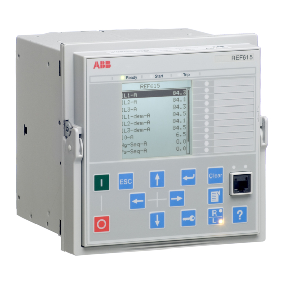
Manuals and User Guides for ABB relion REF615 Feeder Protection Relay. We have
6
ABB relion REF615 Feeder Protection Relay manuals available for free PDF download: Applications Manual, Operation Manual, Point List Manual, Product Manual
ABB relion REF615 Applications Manual (404 pages)
Feeder Protection and Control Relion 615 series
Brand:
ABB
| Category:
Controller
| Size: 6.73 MB
Table of Contents
Table of Contents
7
Section 1 Introduction
13
This Manual
13
Intended Audience
13
Product Documentation
14
Product Documentation Set
14
Document Revision History
14
Related Documentation
15
Symbols and Conventions
15
Symbols
15
Document Conventions
16
Functions, Codes and Symbols
17
Section 2 REF615 Overview
23
Overview
23
Product Version History
24
PCM600 and Relay Connectivity Package Version
25
Operation Functionality
26
Optional Functions
26
Physical Hardware
26
Local HMI
30
Display
31
Leds
32
Keypad
32
Web HMI
32
Authorization
34
Audit Trail
34
Communication
36
Self-Healing Ethernet Ring
37
Ethernet Redundancy
38
Process Bus
40
Secure Communication
42
Section 3 REF615 Standard Configurations
43
Standard Configurations
43
Addition of Control Functions for Primary Devices and the Use of Binary Inputs and Outputs
47
Connection Diagrams
49
Standard Configuration a
55
Applications
55
Functions
56
Default Disturbance Recorder Settings
57
Functional Diagrams
59
Functional Diagrams for Protection
60
Functional Diagrams for Disturbance Recorder
70
Functional Diagrams for Condition Monitoring
71
Functional Diagrams for Control and Interlocking
72
Functional Diagrams for Measurement Functions
74
Functional Diagrams for I/O and Alarm Leds
75
Other Functions
77
Standard Configuration N
77
Applications
77
Functions
78
Default I/O Connections
78
Default Disturbance Recorder Settings
80
Functional Diagrams
82
Functional Diagrams for Protection
82
Functional Diagrams for Disturbance Recorder
92
Functional Diagrams for Condition Monitoring
93
Functional Diagrams for Control and Interlocking
95
Functional Diagrams for Measurement Functions
97
Functional Diagrams for I/O and Alarm Leds
99
Functional Diagrams for Other Timer Logics
102
Other Functions
103
Functions
104
Default Disturbance Recorder Settings
105
Functional Diagrams
107
Functional Diagrams for Disturbance Recorder
113
Functional Diagrams for Condition Monitoring
114
Functional Diagrams for Control and Interlocking
115
Functional Diagrams for Measurement Functions
117
Functional Diagrams for I/O and Alarm Leds
118
Other Functions
120
Functions
121
Default Disturbance Recorder Settings
123
Functional Diagrams
124
Overcurrent Protection
125
Functional Diagrams for Protection
125
Functional Diagrams for Disturbance Recorder
132
Functional Diagrams for Condition Monitoring
133
Functional Diagrams for Control and Interlocking
135
Functional Diagrams for Measurement Functions
138
Functional Diagrams for I/O and Alarm Leds
139
Functional Diagrams for Other Timer Logics
142
Other Functions
143
Functions
144
Default Disturbance Recorder Settings
146
Functional Diagrams
148
Functional Diagrams for Disturbance Recorder
159
Functional Diagrams for Condition Monitoring
160
Functional Diagrams for Control and Interlocking
162
Functional Diagrams for Measurement Functions
165
Functional Diagrams for I/O and Alarm Leds
167
Functional Diagrams for Other Timer Logics
170
Other Functions
171
Functions
172
Default Disturbance Recorder Settings
174
Functional Diagrams
176
Functional Diagrams for Protection
177
Functional Diagrams for Disturbance Recorder
190
Functional Diagrams for Condition Monitoring
191
Functional Diagrams for Control and Interlocking
194
Functional Diagrams for Measurement Functions
196
Functional Diagrams for I/O and Alarm Leds
199
Functional Diagrams for Other Timer Logics
202
Other Functions
203
Functions
204
Default Disturbance Recorder Settings
206
Functional Diagrams
208
Functional Diagrams for Disturbance Recorder
220
Functional Diagrams for Condition Monitoring
221
Functional Diagrams for Control and Interlocking
223
Functional Diagrams for Measurement Functions
226
Functional Diagrams for I/O and Alarm Leds
228
Functional Diagrams for Other Timer Logics
231
Other Functions
232
Functions
233
Default Disturbance Recorder Settings
235
Functional Diagrams
237
Functional Diagrams for Protection
238
Functional Diagrams for Disturbance Recorder
249
Functional Diagrams for Condition Monitoring
250
Functional Diagrams for Control and Interlocking
253
Functional Diagrams for Measurement Functions
256
Functional Diagrams for I/O and Alarm Leds
258
Functional Diagrams for Other Timer Logics
261
Other Functions
262
Functions
263
Default Disturbance Recorder Settings
265
Functional Diagrams
267
Functional Diagrams for Protection
268
Functional Diagrams for Disturbance Recorder
281
Functional Diagrams for Condition Monitoring
282
Functional Diagrams for Control and Interlocking
285
Functional Diagrams for Measurement Functions
288
Functional Diagrams for I/O and Alarm Leds
291
Functional Diagrams for Other Timer Logics
295
Other Functions
296
Functions
297
Default Disturbance Recorder Settings
299
Functional Diagrams
301
Functional Diagrams for Protection
302
Functional Diagrams for Disturbance Recorder
314
Functional Diagrams for Condition Monitoring
315
Functional Diagrams for Control and Interlocking
317
Functional Diagrams for Measurement Functions
321
Functional Diagrams for I/O and Alarm Leds
324
Functional Diagrams for Other Timer Logics
327
Other Functions
328
Functions
329
Default Disturbance Recorder Settings
331
Functional Diagrams
333
Functional Diagrams for Protection
334
Functional Diagrams for Disturbance Recorder
347
Functional Diagrams for Condition Monitoring
348
Functional Diagrams for Control and Interlocking
350
Functional Diagrams for Measurement Functions
353
Functional Diagrams for I/O and Alarm Leds
356
Functional Diagrams for Other Timer Logics
359
Other Functions
360
Functions
361
Default Disturbance Recorder Settings
363
Functional Diagrams
364
Functional Diagrams for Protection
365
Functional Diagrams for Disturbance Recorder
372
Functional Diagrams for Condition Monitoring
373
Functional Diagrams for Control and Interlocking
375
Functional Diagrams for Measurement Functions
377
Functional Diagrams for I/O and Alarm Leds
380
Functional Diagrams for Other Timer Logics
383
Other Functions
384
Non-Directional Overcurrent Protection
386
Example for Non-Directional Overcurrent Protection
387
Section 5 IED Physical Connections
389
Phase Voltages
390
Binary Inputs
391
Optional Light Sensor Inputs
393
Rtd/Ma Inputs
394
Outputs
395
Section 6 Glossary
399
Advertisement
ABB relion REF615 Applications Manual (240 pages)
Feeder Protection and Control
Brand:
ABB
| Category:
Protection Device
| Size: 13.78 MB
Table of Contents
Table of Contents
7
Section 1 Introduction
13
This Manual
13
Intended Audience
13
Product Documentation
14
Product Documentation Set
14
Document Revision History
15
Related Documentation
16
Document Symbols and Conventions
16
Safety Indication Symbols
16
Document Conventions
17
Functions, Codes and Symbols
17
Section 2 REF615 Overview
21
Overview
21
Product Version History
22
PCM600 and IED Connectivity Package Version
22
Operation Functionality
22
Standard Configurations
22
Optional Functions
24
Physical Hardware
25
Lhmi
27
Lcd
27
Leds
28
Keypad
28
Whmi
29
Authorization
30
Communication
31
Section 3 REF615 Variants
33
REF615 Variant List
33
Presentation of Standard Configurations
33
Standard Configurations
34
Connection Diagrams
37
Standard Configuration a Including Directional Earth-Fault Protection
40
Applications
40
Functions
41
Default I/O Connections
42
Functional Diagrams
42
Functional Diagrams for Protection
43
Functional Diagrams for Disturbance Recorder and Trip Circuit Supervision
48
Functional Diagrams for Control and Interlocking
49
Standard Configuration B Including Directional Earth-Fault Protection and CB Condition Monitoring
51
Applications
51
Functions
51
Default I/O Connections
52
Functional Diagrams
53
Functional Diagrams for Protection
53
Functional Diagram for Disturbance Recorder and Trip Circuit Supervision
59
Functional Diagrams for Control and Interlocking
60
Standard Configuration C Including Non-Directional Earth-Fault
64
Protection
64
Applications
64
Functions
64
Default I/O Connections
65
Functional Diagrams
66
Functional Diagrams for Protection
66
Functional Diagram for Disturbance Recorder and Trip Circuit Supervision
71
Functional Diagrams for Control and Interlocking
72
Standard Configuration D Including Non-Directional Earth-Fault Protection and CB Condition Monitoring
74
Applications
74
Functions
74
Default I/O Connections
75
Functional Diagrams
76
Functional Diagrams for Protection
76
Functional Diagram for Disturbance Recorder and Trip Circuit Supervision
81
Functional Diagrams for Control and Interlocking
82
Standard Configuration E Including Directional Earth-Fault Protection with Phase-Voltage Measurement
86
Applications
86
Functions
86
Default I/O Connections
87
Functional Diagrams
88
Functional Diagrams for Protection
88
Functional Diagram for Disturbance Recorder and Trip Circuit Supervision
94
Functional Diagrams for Control and Interlocking
95
Standard Configuration F Including Directional Overcurrent Protection with Voltage Protection
99
Default I/O Connections
101
Functional Diagrams
102
Functional Diagram for Disturbance Recorder and Trip Circuit Supervision
108
Functional Diagrams for Control and Interlocking
110
General Parameters
117
Self-Supervision
132
Internal Faults
133
Warnings
134
Time Synchronization
135
Parameter Setting Groups
136
Three-Phase Current Protection
139
Three-Phase Directional Overcurrent Protection Dphxpdoc
146
Three-Phase Thermal Overload Protection for Overhead Lines and Cables T1PTTR
149
Application
150
Earth-Fault Protection
151
Directional Earth-Fault Protection Defxpdef
152
Application
158
Transient/Intermittent Earth-Fault Protection INTRPTEF
160
Functionality
161
Unbalance Protection
164
Functionality
165
Functionality
166
Arc Protection ARCSARC
168
Voltage Protection
172
Functionality
173
Functionality
174
Residual Overvoltage Protection ROVPTOV
175
Negative Sequence Overvoltage Protection NSPTOV
176
Positive Sequence Undervoltage Protection PSPTUV
177
Three-Phase Inrush Detector INRPHAR
187
Circuit Breaker Failure Protection CCBRBRF
188
Application
189
Protection Trip Conditioning TRPPTRC
190
Application
191
Trip Circuit Supervision TCSSCBR
193
Current Circuit Supervision CCRDIF
200
Application
201
Fuse Failure Supervision SEQRFUF
205
Application
206
Circuit Breaker Condition Monitoring SSCBR
207
Basic Measurements
211
Sequence Current CSMSQI
212
Measurement Function Applications
213
Disturbance Recorder
214
Circuit Breaker Control CBXCBR
217
Disconnector DCSXSWI and Earthing Switch ESSXSWI
218
Application
219
Auto Recloser DARREC
220
Shot Initiation
221
Sequence
223
Configuration Examples
224
Delayed Initiation Lines
227
Shot Initiation from Protection Start Signal
229
Current Transformers
231
Non-Directional Overcurrent Protection
232
Example for Non-Directional Overcurrent Protection
233
Section 12 Glossary
235
ABB relion REF615 Applications Manual (220 pages)
Feeder Protection and Control Relay
Brand:
ABB
| Category:
Relays
| Size: 6.94 MB
Table of Contents
Table of Contents
7
Section 1 Introduction
11
This Manual
11
Intended Audience
11
Product Documentation
12
Product Documentation Set
12
Document Revision History
12
Related Documentation
13
Symbols and Conventions
13
Symbols
13
Document Conventions
14
Functions, Codes and Symbols
14
Section 2 REF615 Overview
21
Overview
21
Product Version History
22
PCM600 and Relay Connectivity Package Version
23
Operation Functionality
23
Optional Features
23
Physical Hardware
24
Local HMI
27
Display
28
Leds
29
Keypad
29
Web HMI
30
Authorization
31
Communication
32
Self-Healing Ethernet Ring
33
Ethernet Redundancy
34
Section 3 REF615 Standard Configurations
37
Standard Configurations
37
Addition of Control Functions for Primary Devices and the Use of Binary Inputs and Outputs
41
Connection Diagrams
43
Standard Configuration D
48
Applications
48
Functions
48
Default I/O Connections
49
Default Disturbance Recorder Settings
50
Functional Diagrams
53
Functional Diagrams for Protection
53
Functional Diagrams for Disturbance Recorder
62
Functional Diagrams for Condition Monitoring
63
Functional Diagrams for Control and Interlocking
65
Functional Diagrams for Measurement Functions
67
Functional Diagrams for I/O and Alarm Leds
68
Functional Diagrams for Other Functions
71
Functional Diagrams for Other Timer Logics
71
Functional Diagrams for Communication
72
Standard Configuration F
73
Applications
73
Functions
73
Default I/O Connections
74
Default Disturbance Recorder Settings
76
Functional Diagrams
78
Functional Diagrams for Protection
79
Functional Diagrams for Disturbance Recorder
93
Functional Diagrams for Condition Monitoring
94
Functional Diagrams for Control and Interlocking
96
Functional Diagrams for Measurement Functions
98
Functional Diagrams for I/O and Alarm Leds
100
Functional Diagrams for Other Functions
103
Functional Diagrams for Other Timer Logics
103
Functional Diagrams for Communication
105
Standard Configuration L
105
Applications
105
Functions
106
Default I/O Connections
106
Default Disturbance Recorder Settings
108
Functional Diagrams
110
Functional Diagrams for Protection
111
Functional Diagrams for Disturbance Recorder
127
Functional Diagrams for Condition Monitoring
128
Functional Diagrams for Control and Interlocking
130
Functional Diagrams for Measurement Functions
133
Functional Diagrams for I/O and Alarm Leds
135
Functional Diagrams for Other Functions
137
Functional Diagrams for Other Timer Logics
137
Functional Diagrams for Communication
138
Standard Configuration N
139
Applications
139
Functions
139
Default I/O Connections
140
Default Disturbance Recorder Settings
142
Functional Diagrams
144
Functional Diagrams for Protection
145
Functional Diagrams for Disturbance Recorder
159
Functional Diagrams for Condition Monitoring
159
Functional Diagrams for Control and Interlocking
162
Functional Diagrams for Measurement Functions
164
Functional Diagrams for I/O and Alarm Leds
166
Functional Diagrams for Other Functions
169
Functional Diagrams for Other Timer Logics
169
Functional Diagrams for Communication
170
Standard Configuration P
171
Applications
171
Functions
171
Default I/O Connections
172
Default Disturbance Recorder Settings
174
Functional Diagrams
176
Functional Diagrams for Protection
177
Functional Diagrams for Disturbance Recorder
188
Functional Diagrams for Condition Monitoring
189
Functional Diagrams for Control and Interlocking
192
Functional Diagrams for Measurement Functions
194
Functional Diagrams for I/O and Alarm Leds
196
Functional Diagrams for Other Timer Logics
201
Functional Diagrams for Communication
202
Section 4 Requirements for Measurement Transformers
203
Current Transformers
203
Current Transformer Requirements for Overcurrent Protection
203
Current Transformer Accuracy Class and Accuracy Limit Factor
203
Non-Directional Overcurrent Protection
204
Example for Non-Directional Overcurrent Protection
205
Section 5 Protection Relay's Physical Connections
207
Inputs
207
Energizing Inputs
207
Phase Currents
207
Ground Current
207
Phase Voltages
207
Ground Voltage
208
Sensor Inputs
208
Auxiliary Supply Voltage Input
208
Binary Inputs
209
Optional Light Sensor Inputs
211
Rtd/Ma Inputs
212
Outputs
213
Outputs for Tripping and Controlling
213
Outputs for Signalling
214
Irf
215
Section 6 Glossary
217
Advertisement
ABB relion REF615 Operation Manual (126 pages)
615 series
Brand:
ABB
| Category:
Control Unit
| Size: 3.4 MB
Table of Contents
Safety Information
7
Table of Contents
9
Section 1 Introduction
15
This Manual
15
Intended Audience
15
Product Documentation
16
Product Documentation Set
16
Document Revision History
17
Related Documentation
17
Document Symbols and Conventions
18
Safety Indication Symbols
18
Document Conventions
18
Functions, Codes and Symbols
19
Section 2 Environmental Aspects
21
Sustainable Development
21
Disposing of the IED
21
Section 3 615 Series Overview
23
Overview
23
Lhmi
24
Lcd
24
Leds
26
Keypad
26
LHMI Functionality
29
Protection and Alarm Indication
29
Front Communication
30
Parameter Management
30
Whmi
31
Command Buttons
32
Authorization
33
Communication
34
PCM600 Configuration Tool
35
Connectivity Packages
35
PCM600 and IED Connectivity Package Version
36
Section 4 Using HMI Locally or Via Web Interface
37
Using LHMI
37
Logging in
37
Logging out
38
Turning Display Backlight on
39
Selecting Local or Remote Use
39
Identifying the Device
40
Adjusting Display Contrast
41
Changing LHMI Language
41
Changing Display Symbols
42
Navigating in the Menu
42
Menu Structure
43
Scrolling the LCD View
43
Browsing Setting Values
44
Changing the Default View
44
Editing Values
44
Editing Numerical Values
45
Editing Enumerated Values
46
Editing String Values
46
Committing Settings
47
Clearing and Acknowledging
48
Using LHMI Help
48
Using WHMI
49
Logging in
49
Logging out
49
Identifying the Device
50
Navigating in the Menu
51
Menu Structure
52
Showing All Parameters
52
Editing Values
54
Committing Settings
56
Clearing and Acknowledging
58
Selecting Alarm View
59
Selecting Event View
60
Selecting the Disturbance Record View
61
Uploading Disturbance Records
62
Triggering the Disturbance Recorder Manually
63
Deleting Disturbance Records
64
Selecting Phasor Diagrams
65
Selecting Disturbance Records
69
Using WHMI Help
69
Section 5 IED Operation
71
Normal Operation
71
Disturbance Identification
71
Disturbance Recording Triggering
72
Disturbance Record Analysis
72
Disturbance Reports
72
Internal IED Errors
72
IED Parametrization
73
IED Settings for IED Functionality
73
IED Settings for Different Operating Conditions
74
Section 6 Operating Procedures
75
Monitoring
75
Indications
75
Monitoring Indication Messages
75
Monitoring an Internal IED Fault
76
Monitoring Condition Monitoring Data
76
Measured and Calculated Values
76
Measured Values
76
Using LHMI for Monitoring
77
Recorded Data
77
Creating Disturbance Recordings
78
Monitoring Disturbance Recorder Data
78
Controlling and Uploading Disturbance Recorder Data
79
Monitoring Fault Records
79
Monitoring Events
80
Remote Monitoring
80
Operating IED Remotely
80
Controlling
81
Controlling Circuit Breakers and Disconnectors
81
Resetting IED
82
Clearing and Acknowledging Via LHMI
82
Changing IED Functionality
83
Defining Setting Group
83
Activating a Setting Group
83
Copying a Setting Group
84
Selecting a Setting Group for Editing
84
Browsing and Editing Setting Group Values
85
Activating Leds
87
Section 7 Troubleshooting
89
Fault Tracing
89
Identifying Hardware Errors
89
Identifying Runtime Errors
89
Identifying Communication Errors
89
Checking the Communication Link Operation
89
Checking the Time Synchronization
90
Running the Display Test
90
Indication Messages
90
Internal Faults
90
Warnings
92
LED and Display Messages
94
Correction Procedures
94
Rebooting Software
94
Restoring Factory Settings
94
Setting Password
94
Identifying IED Application Problems
95
Inspecting Wiring
95
Sample Data Interruptions
95
Section 8 Commissioning
97
Commissioning Checklist
97
Checking Installation
97
Checking the Power Supply
97
Checking CT Circuits
98
Checking VT Circuits
98
Checking Binary Input and Output Circuits
99
Binary Input Circuits
99
Binary Output Circuits
99
Authorizations
99
User Authorization
99
Using PCM600
100
Setting Communication between Ieds and PCM600
100
Communication Options
101
Setting Communication Parameters
101
Setting IED and Communication
106
Communication Settings
106
Serial Communication Ports and Drivers
106
Serial Link Diagnostics and Monitoring
107
Connecting Jumper Connectors
110
Defining Ethernet Port Settings
110
Defining Serial Port Settings
110
Setting Communication Protocol Parameters
110
Adjusting Display Contrast
111
Changing Display Symbols
111
Changing LHMI Language
111
Setting LHMI
111
Changing the Default View
112
Setting System Time and Time Synchronization
112
Defining Setting Groups
113
Setting IED Parameters
113
IED Parametrization
116
Configuring Analog Inputs
117
Defining Disturbance Recorder Channel Settings
117
Testing IED Operation
117
Selecting Test Mode
117
Testing Digital I/O Interface
118
Testing Functions
119
Selecting Internal Fault Test
119
ABB Product Data Registration
120
Section 9 Glossary
121
ABB relion REF615 Point List Manual (64 pages)
Feeder Protection and Control
Brand:
ABB
| Category:
Industrial Equipment
| Size: 2.77 MB
Table of Contents
Table of Contents
7
Section 1 Introduction
13
This Manual
13
Intended Audience
13
Product Documentation
13
Product Documentation Set
13
Document Revision History
14
Related Documentation
14
Symbols and Conventions
15
Symbols
15
Document Conventions
15
Functions, Codes and Symbols
16
Section 2 DNP3 Data Mappings
19
Overview
19
Supported Functions
19
Point List for REF615 Ver.4.0 FE01-09
21
Binary Inputs
21
Ctrl.cxxxxx1 Circuit Breaker (1) CB Object and Failure Protection
22
LD0.ARCSARC1 Fault Arc Protection Stage 1
22
LD0.ARCSARC2 Fault Arc Protection Stage 2
22
LD0.ARCSARC3 Fault Arc Protection Stage 3
22
Ctrl.dxxxxx1 Controllable Disconnector (1)
23
Ctrl.dxxxxx2 Controllable Disconnector (2)
23
CTRL.CCRDIF1 Current Circuit Failure Protection
24
Ctrl.exxxxx1 Controllable Earth Switch (1)
24
LD0.CMHAI1 Power Quality - Current Total Demand Distortion
24
LD0.CMMXU1 Phase Currents (1) Limit Supervision
24
LD0.DARREC1 Autorecloser
25
LD0.DEFHPDEF1 Directional Earth-Fault Protection - High Stage 1
25
LD0.DEFLPDEF1 Directional Earth-Fault Protection - Low Stage 1
26
LD0.DEFLPDEF2 Directional Earth-Fault Protection - Low Stage 2
26
LD0.DPHLPDOC1 Three-Phase Directional Overcurrent Protection - Low Stage (1)
26
LD0.DPHLPDOC2 Three-Phase Directional Overcurrent Protection - Low Stage (2)
26
LD0.DPHHPDOC1 Three-Phase Directional Overcurrent Protection - High Stage (1)
27
LD0.EFHPTOC1 Non-Directional Earth-Fault and Sensitive Earth-Fault Protection - High Stage 1
27
LD0.EFIPTOC1 Non-Directional Earth-Fault and Sensitive Earth-Fault Protection - Instantaneous Stage 1
27
LD0.EFLPTOC1 Non-Directional Earth-Fault and Sensitive Earth-Fault Protection - Low Stage 1
27
LD0.EFLPTOC2 Non-Directional Earth-Fault and Sensitive Earth-Fault Protection - Low Stage 2
28
LD0.EFPADM1 Admittance-Based Earth-Fault Protection (1)
28
LD0.EFPADM2 Admittance-Based Earth-Fault Protection (2)
28
LD0.EFPADM3 Admittance-Based Earth-Fault Protection (3)
28
LD0.FRPFRQ1 Frequency Protection (1)
28
LD0.FRPFRQ2 Frequency Protection (2)
29
LD0.FRPFRQ3 Frequency Protection (3)
29
LD0.HAEFPTOC1 Harmonics-Based Earth-Fault Protection
29
LD0.INPHAR1 Three-Phase Inrush Detection
30
LD0.INTRPTEF1 Transient/Intermittent Earth-Fault Protection
30
LD0.LEDGGIO1 LHMI LED Indications
30
LD0.LEDPTRC1 Global Protection Signals
30
CTRL.LLN0 Local/Remote State (also Present in DNP IIN-Bits)
31
LD0.LLN0 Settings Supervision
31
LD0.MVGAPC1 Multipurpose Binary Inputs (1)
31
LD0.MVGAPC2 Multipurpose Binary Inputs (2)
32
LD0.NSPTOC1 Negative-Sequence Overcurrent Protection (1)
32
LD0.NSPTOC2 Negative-Sequence Overcurrent Protection (2)
32
LD0.NSPTOV1 Negative-Sequence Overvoltage Protection - Stage 1
32
LD0.PDNSPTOC1 Phase Discontinuity Protection
33
LD0.PHHPTOC1 Phase Overcurrent Protection - High Stage 1
33
LD0.PHHPTOC2 Phase Overcurrent Protection - High Stage 2
33
LD0.PHIPTOC1 Phase Overcurrent Protection - Instantaneous Stage 1
33
LD0.PHLPTOC1 Phase Overcurrent Protection - Low Stage 1
33
LD0.PHPTOV1 Phase Overvoltage Protection - Stage 1
34
LD0.PHPTOV2 Phase Overvoltage Protection - Stage 2
34
LD0.PHPTOV3 Phase Overvoltage Protection - Stage 3
34
LD0.PHPTUV1 Phase Undervoltage Protection - Stage 1
34
LD0.PHPTUV2 Phase Undervoltage Protection - Stage 2
34
LD0.PHPTUV3 Phase Undervoltage Protection - Stage 3
35
LD0.PSPTUV1 Positive-Sequence Undervoltage Protection - Stage 1
35
LD0.PH1QVVR1 PQ - Voltage Variation Signals
35
DR.RDRE1 Disturbance Recorder
35
LD0.RESCMMXU1 Residual Current Limit Supervision
35
LD0.RESVMMXU1 Residual Voltage Limit Supervision
36
LD0.ROVPTOV1 Residual Overvoltage Protection (1)
36
LD0.ROVPTOV2 Residual Overvoltage Protection (2)
36
LD0.ROVPTOV3 Residual Overvoltage Protection (3)
36
LD0.SECRSYN1 Synchrocheck
36
LD0.SEQRFUF1 Fuse Failure Protection
37
LD0.SPCGGIO2 Multipurpose Binary Outputs - Status (2)
37
LD0.SSCBR1 Circuit-Breaker Condition Monitoring
37
LD0.T1PTTR1 Thermal Protection (1)
38
LD0.TCSSCBR1 Trip Circuit Supervision (1)
38
LD0.TCSSCBR2 Trip Circuit Supervision (2)
38
LD0.TRPPTRC1 Global Conditioning (1)
38
LD0.TRPPTRC2 Global Conditioning (2)
39
LD0.VMHAI1 PQ - Voltage Total Harmonic Distortion
39
LD0.VMMXU1 Three-Phase Voltage Limit Supervision
39
LD0.WPWDE1 Wattmetric-Based Earth-Fault Protection (1)
39
LD0.WPWDE2 Wattmetric-Based Earth-Fault Protection (2)
39
LD0.WPWDE3 Wattmetric-Based Earth-Fault Protection (3)
40
LD0.XAGGIO130 Physical I/O
40
LD0.XGGIO100 Physical I/O
40
LD0.XGGIO110 Physical I/O
40
LD0.XGGIO120 Physical I/O
41
LD0.XGGIO130 Physical I/O
41
Binary Outputs
42
CTRL.CBCSWI1 Circuit Breaker Control
42
CTRL.DCCSWI1 Controllable Disconnector (1) Control
42
CTRL.DCCSWI2 Controllable Disconnector (2) Control
42
CTRL.ESCSWI2 Controllable Earth Switch (1) Control
42
LD0.DARREC1 Autoreclosing Reset Signals
43
LD0.DNPGGIO1 Parameter Setting Group Control
43
LD0.LLN0/LPHD1 Reset Indications and Leds, Reset Device
43
LD0.PEMMXU1 Reset Accumulated Energy Values
43
DR.RDRE1 Disturbance Recorder
44
LD0.SPCGGIO1 Multipurpose Binary Outputs (1)
44
LD0.SPCGGIO2 Multipurpose Binary Outputs (2)
44
LD0.SRGAPC1 Multipurpose Binary Outputs - Flip-Flop Resets (1)
45
LD0.SRGAPC2 Multipurpose Binary Outputs - Flip-Flop Resets (2)
46
LD0.SSCBR1 Reset Signals of CB Condition Monitoring
46
Analog Inputs
46
CTRL.CBCSWI1 CB 4-Pole (2 Bit) Position Value
47
CTRL.DCSXSWI1 Disconnector 1, 4-Pole (2 Bit) Position Values
47
LD0.CMMXU1 Phase Currents (1)
47
LD0.CSMSQI1 Sequence of Currents
47
LD0.DARREC1 Autoreclosing Values
47
CTRL.DCSXSWI2 Disconnector 2, 4-Pole (2 Bit) Position Values
48
CTRL.DCSXSWI3 Disconnector 3, 4-Pole (2 Bit) Position Values
48
CTRL.DCXSWI1 Controllable Disconnector 1, 4-Pole (2 Bit) Position Values
48
CTRL.DCXSWI2 Controllable Disconnector 2, 4-Pole (2 Bit) Position Values
48
CTRL.ESSXSWI1 Earth Switch 1, 4-Pole (2 Bit) Position Values
48
CTRL.ESSXSWI2 Earth Switch 2, 4-Pole (2 Bit) Position Values
49
CTRL.ESXSWI1 Controllable Earth Switch 1, 4-Pole (2 Bit) Position Values
49
LD0.DNPGGIO1 Active Parameter Setting Group
49
LD0.FMMXU1 Frequency Measurement
49
LD0.HAEFMHAI1 Current Harmonics
49
CTRL.LLN0 Local Remote Station off
50
DR.RDRE1 Disturbance Recorder Values
50
LD0.LPHD1 System Values
50
LD0.PEMMTR1 Power Measurement and Accumulated Power Values
50
LD0.RESCMMXU1 Residual Current (1)
51
LD0.RESVMMXU1 Residual Voltage (1)
51
LD0.SECRSYN1 Synchrocheck Line and Bus State
51
LD0.T1PTTR1 Temperature Protection Values (1)
51
LD0.VMMXU1 Voltage Measurement
51
LD0.VSMSQI1 Sequence of Voltage Measurement
52
Section 3 DNP3 Protocol Implementation
53
DNP3 Device Profile
53
DNP3 Implementation Table
55
Section 4 Glossary
59
ABB relion REF615 Product Manual (57 pages)
Feeder Protection and Control
Brand:
ABB
| Category:
Protection Device
| Size: 4.03 MB
Table of Contents
Table of Contents
2
Supported Functions
3
Description
3
Standard Configurations
3
Functionality Protection
4
Functionality
5
Protection Functions
6
Application
9
Event Log/Recorded Data
12
Control
12
Measurement
12
Disturbance Recorder
12
Trip-Circuit Supervision/Self-Supervision
13
Circuit-Breaker Monitoring
13
Fuse Failure Supervision
13
Current Circuit Supervision
13
Access Control
14
Inputs and Outputs
14
Communication
14
Supported Communication Interfaces and Protocols
16
Dimensions
17
Power Supply
17
Technical Data
17
Energizing Inputs
18
Binary Inputs
18
Signal Output X100: SO1
18
Lens Sensor and Optic Fiber for Arc Protection
19
Single-Pole Power Output Relays
19
Double-Pole Power Output Relay with TCS Function
19
Signal Outputs and IRF Output
19
Degree of Protection of Flush-Mounted IED
20
Environmental Conditions
20
Environmental Tests
20
Electromagnetic Compatibility Tests
20
Insulation Tests
22
Mechanical Tests
22
Ethernet Interfaces
22
Three-Phase Non-Directional Overcurrent Protection (Phxptoc)
23
Three-Phase Directional Overcurrent Protection (Dphxpdoc)
25
Non-Directional EF Protection (Efxptoc)
26
Non-Directional EF Protection (Efxptoc) Main Settings
26
Directional EF Protection (Defxpdef)
27
Directional EF Protection (Defxpdef) Main Settings
28
Transient/Intermittent Earth-Fault Protection (INTRPTEF)
28
Three-Phase Overvoltage Protection (PHPTOV)
29
Three-Phase Overvoltage Protection (PHPTOV) Main Settings
29
Positive Sequence Undervoltage Protection (PSPTUV)
30
Three-Phase Undervoltage Protection (PHPTUV)
30
Negative Sequence Overvoltage Protection (NSPTOV)
31
Residual Overvoltage Protection (ROVPTOV)
32
Negative Phase-Sequence Current Protection (NSPTOC)
32
Phase Discontinuity Protection (PDNSPTOC)
33
Circuit Breaker Failure Protection (CCBRBRF)
34
Three-Phase Thermal Overload (T1PTTR)
34
Three-Phase Inrush Current Detection (INRPHAR)
35
Arc Protection (ARCSARC)
35
Autoreclosure (DARREC)
36
Operating Characteristics
36
Control Functions
36
Measurement Functions
37
Supervision Functions
38
Current Circuit Supervision (CCRDIF)
38
Current Circuit Supervision (CCRDIF) Main Settings
38
Fuse Failure Supervision (SEQRFUF)
38
Display Options
39
Mounting Methods
40
IED Case and IED Plug-In Unit
40
Selection and Ordering Data
41
Accessories and Ordering Data
44
Tools
44
Supported ABB Solutions
46
Terminal Diagrams
47
Certificates
50
References
50
Functions, Codes and Symbols
51
Advertisement
Related Products
ABB RED670 Relion 670 series
ABB REC603
ABB REC601
ABB Relion REM601
ABB Relion RED615
ABB RSD100 Contrac
ABB RVC
ABB RTC-F-1.PB
ABB Contrac RSD 200-5,0
ABB RHDE2500-10
ABB Categories
Industrial Equipment
Controller
Measuring Instruments
Battery Charger
DC Drives
More ABB Manuals
Login
Sign In
OR
Sign in with Facebook
Sign in with Google
Upload manual
Upload from disk
Upload from URL