Sign In
Upload
Manuals
Brands
ABB Manuals
Protection Device
REG316 4 Series
ABB REG316 4 Series Manuals
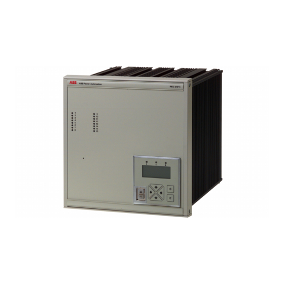
Manuals and User Guides for ABB REG316 4 Series. We have
1
ABB REG316 4 Series manual available for free PDF download: Operating Instructions Manual
ABB REG316 4 Series Operating Instructions Manual (980 pages)
Numerical Generator Protection
Brand:
ABB
| Category:
Protection Device
| Size: 10.43 MB
Table of Contents
2. Description of Hardware
11
Table of Contents
11
Mechanical Design
14
Hardware Versions
14
Construction
14
Casing and Methods of Mounting
14
Front of the Protection
14
PC Connection
15
Test Facilities
15
Auxiliary Supply Unit
16
Input Transformer Unit
16
Main Processor Unit
17
Binary I/O Unit
18
Interconnection Unit
18
Injection Unit REX 010
19
Injection Transformer Block REX 011
23
Rex011
29
Rex011-1, -2
35
Testing Without the Generator
37
3. Setting the Functions
39
General
42
Library and Settings
42
Setting the Functions
42
Control and Protection Function Sequence
43
Repetition Rate
43
Computation Requirement of Protection Functions
44
Computing Capacity Required by the Control Function
47
C.t./V.t. Inputs
48
Protection Function Inputs and Outputs
48
Binary Inputs
49
Signalling Outputs
49
Frequency Range
50
Measured Values
50
Tripping Outputs
50
Configuring the Hardware
51
System Parameter Settings
51
Entering the C.t./V.t. Channels
56
Entering Comments for Binary Inputs and Outputs
57
Edit System Parameters
58
Masking Binary Inputs, Entering Latching Parameters and Definition of "Double Indications
58
Edit System I/O
59
Edit System Name
62
Edit System Password
62
Protection Functions
63
Transformer Differential Protection Function
63
Generator Differential
91
Definite Time over and Undercurrent
97
Peak Value Overcurrent
103
Voltage-Controlled Overcurrent
109
Inverse Time Overcurrent
117
Directional Definite Time Overcurrent Protection
123
Directional Inverse Time Overcurrent Protection
131
Definite Time NPS
143
Inverse Time NPS
149
Definite Time over and Undervoltage
155
Definite Time Stator Earth Fault (95 %)
160
Rotor E/F Protection
173
Interturn Protection
175
Peak Value Overvoltage
177
Underimpedance
183
Underreactance
191
Power
203
Stator Overload
217
Rotor Overload
223
Frequency Protection
229
Rate-Of-Change of Frequency Protection
235
Overfluxing
239
Inverse Time Overfluxing
243
Balanced Voltage
249
Overtemperature Protection
257
Stator Ground Fault
265
Rotor Ground Fault Protection by Injection
287
Pole Slipping
297
Inverse Definite Minimum Time Earth Fault Overcurrent Function
309
Breaker Failure Protection
315
Control Function
331
Control Functions
331
Control Function Settings - FUPLA
333
General
334
Binary Inputs
335
Binary Signals
335
Timers
335
Flow Chart for Measurement Inputs and Outputs
336
Measurement Inputs
336
Measurement Outputs
336
Loading FUPLA
337
Logic
339
Delay / Integrator
343
Contact Bounce Filter
349
LDU Events
353
Counter
357
Measurement Function
361
Measurement Functions
361
Three-Phase Current Plausibility
367
Three-Phase Voltage Plausibility
371
Disturbance Recorder
375
Measurement Module
389
Impulse Counter Inputs
395
Impulse Counter Operating Principle
396
Impulse Counter Operation
396
Interval Processing
397
4. Description of Function and Application
399
General
402
High-Impedance
402
Protection Functions
402
Basic Requirements
403
Components of a Restricted E/F Scheme
403
Design
403
Restricted E/F Protection for a Transformer
403
General
409
Standstill Protection
409
Standstill Protection Using an Overcurrent Function
410
Application
411
Determining the Settings
411
Rotor Ground Fault Protection
411
Functional Check
412
Recommended Settings for R F , Respectively 'U-Setting' and T
412
Required Data
412
Checking the Wiring
413
Connection of a Two-Stage Scheme
413
Installation and Wiring
413
Location and Ambient Conditions
413
Adaptation of the Scheme in the Case of Shaft Filters
414
Commissioning
414
Connection to Excitation Systems with Shaft-Mounted Diodes
414
Pre-Commissioning Checks
414
Calibration of the Ancillary Unit Type YWX111-11/-21
415
Measuring the Voltage Values
416
Testing in Operation
417
Fault-Finding
419
Likely Causes of Problems
419
Maintenance
419
Accessories and Spares
420
Appendices
420
Application of the Underreactance Protection Function
424
Introduction
424
Monitoring a Given Load Angle
424
Out-Of-Step Conditions
424
Principle of Operation
429
Stator Ground Fault Protection for Generators in Parallel
429
Busbar Ground Faults
431
Ferroresonance Damping Resistor R P
431
Ground Fault Protection During Start-Up
431
Grounding Transformer
431
Contactor
432
Grounding Resistor R E
432
Residual Current C.t
432
Protection Sensitivity
433
Required REG 316*4 Functions
433
100% Stator and Rotor Ground Fault Protection
437
Breaker Failure Protection
440
Introduction
440
Redundant Trip
441
Three-Phase/ Single-Phase Mode
441
Backup Trip
442
Remote Trip
442
Retrip
442
Unconditional Trip
442
End Fault Trip
443
External Trip
443
5. Operation (Hmi)
445
Installation and Starting the Operator Program
450
Installing the Operator Program
450
PC Requirements
450
Starting and Shutting down the Operator Program
453
General
455
Operation
455
Standard Key Functions Applicable to All Menus
455
Information Displayed on the Screen
456
Using the Mouse
456
Main Menu and Sub-Menus
457
Editor
464
Present Prot. Funcs
465
Changing a Function Comment
467
Changing the Settings of a Function
467
Copying a Function
469
Deleting a Function
470
Adding a New Function
472
General Information on Editing Parameters
472
Entering Numerical Settings
473
Selecting from a List of Alternatives
474
C.t./V.t. Input Channels
476
Explanation of the Types of Channels
476
Signalling Channels
477
Tripping Channels
483
Binary Channels
484
Editing Hardware Functions
491
Inserting a Channel Comment
496
Analog (CT/VT) Channels
497
Excluding (Masking) Binary Channels as Events
498
Definition of Double Signals
499
Tripping and Signalling Channel Latching
499
Editing System Functions
502
Listing Settings
505
Saving the Contents of the Editor
506
Downloading to the Device
507
Saving in and Loading from a File
507
Event Handling and Operation of the Disturbance Recorder
508
Displaying AD(CT/VT) Channels
513
Displaying Variables
513
Displaying Load Values
514
Displaying Analogue Inputs and Outputs
515
Displaying Binary Inputs, Signalling Relays, Led's or Tripping Relays
515
Displaying ITL Inputs and Outputs
516
Displaying SCS Outputs
517
Displaying FUPLA Signals
518
Diagnostics
519
Test Functions
520
Documentation
527
Operation with Several Sets of Parameters
528
Switching Sets of Parameters
528
Assigning a Protection Function to a Set of Parameters
529
Creating Sets of Parameters
529
Copying a Protection Function with Its Settings
530
Displaying a Function with Its Settings
531
Logics
531
Configuring a New Station
533
Installation
533
Remote HMI Shell
533
Establishing the Connection to the Station
538
Configuring a Remote HMI for Operation Via the SPA-BUS Interface
539
Remote HMI Connected Directly to the Electro-Optical Converter
539
Remote HMI Connected Via a Modem to the Electro-Optical Converter
540
Configuring a Remote HMI Connected to an SRIO
541
Remote HMI Connected Directly to the SRIO
541
Remote HMI Connected Via a Modem to the SRIO
542
Control Via an SPA-BUS or an SRIO
543
Local Control of a Device Via the Interface at the Front
543
Remote HMI Right of Access to Device Functions
543
HMI Start-Up
544
Spacomm Window
545
General Description
547
Limitations
547
Local Display Unit
547
Mechanical Assembly and Front View
547
Electrical Connections
548
Passive Operation
548
Password
548
LDU Keypad
549
General
550
The Three Status Led's
550
No Active Protection Functions
551
Normal Operation
551
Pick-Up of a Protection Function (General Start)
551
Protection Function Trip (General Trip)
551
Fatal Device Error
552
General
552
Interdependencies
552
Language
552
Text Display (LCD)
552
Configuration
553
Menu Structure
553
Entry Menu
554
Main Menu
554
AD-Channels
556
Binary Signals
556
Eventlist
556
Measurands
556
User's Guide
562
Diagnosis Information
563
Diagnostics Menu
563
Disturbance Recorder List
563
IBB Status Information
564
Process Bus Information
564
LED Descriptions
565
RESET Menu
566
Automatic Display
567
Automatic Display Cycle
567
Automatic Display Sequence
567
General Description
567
Stopping the Automatic Display Routine
567
Installing SMS010 and 'Reporting' and 'SM/RE.316*4' for SMS010
568
Sms010
568
Main Menu
569
SMS010 Editor
569
Sub-Menu 'SMS010 Editor
570
Descriptions of the Various Menu Items
571
Menu Item 'Edit Event. Dsc' for Processing Event.dsc
571
Menu Item 'Edit Logging. Dsc' for Processing Logging.dsc
573
Menu Item 'Create New DSC Files
574
Creating a Station after Installing SMS010
575
Creating the Application Structure
575
Updating the Spin.cnf File
579
Creating a Report Station
581
Entering the SRIO Address for 'Reporting
582
6. Self-Testing and Monitoring
585
Monitoring the Auxiliary Supply
586
Monitoring the Firmware
586
Self-Testing and Monitoring
586
Summary
586
Diagnostic Events
587
Monitoring the Hardware
587
Device Diagnosis
590
HEX Dump
592
IBB Information
592
SPA Bus
592
LON Bus
593
Mvb
595
Resetting SCS Data
597
RIO Information
597
VDEW Bus
597
Load SCS Mask
598
7. Installation and Maintenance
599
Checking the Shipment
601
Installation
601
Place of Installation and Ambient Conditions
601
Guidelines for RF Grounding
602
Guidelines for Wiring Rack Assemblies
604
Checking the C.t. Connections
607
Checking the Auxiliary Supply Connections
608
Checking the V.t. Connections
608
Checking the Duty of the Tripping and Signalling Contacts
609
Checking the Opto-Coupler Inputs
609
Commissioning
610
Connecting the Setting and Control PC
610
Minimum PC Requirements
610
PC Connecting Cable
610
Serial Interface Parameters
610
Connecting the Binary Inputs and Outputs
611
Connecting the Equipment to the Auxiliary D.C. Supply
611
Connecting V.t. and C.t. Circuits
612
Commissioning Tests
613
Connecting Optical Fibre Cables for the Longitudinal Differential Protection
613
Fault-Finding
615
Maintenance
615
Stand-By LED on the Frontplate
615
Human/Machine Interface
616
Restarting
617
Deleting the Settings and the Program and Downloading a New Program
619
Settings
619
Software Updates
619
Problems Transferring the New Software
621
Replacing Hardware Units
623
Advertisement
Advertisement
Related Products
ABB REG650 ANSI
ABB REG670 2.0 IEC
ABB Relion REG670
ABB RELION REG615
ABB REG670 Customized
ABB REG670 A20
ABB REG670 B30
ABB REG670 C30
ABB RELION 650 SERIES
ABB RET650 2.2
ABB Categories
Industrial Equipment
Controller
Measuring Instruments
Battery Charger
DC Drives
More ABB Manuals
Login
Sign In
OR
Sign in with Facebook
Sign in with Google
Upload manual
Upload from disk
Upload from URL