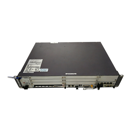
Huawei BBU3900 Installation Manual
Hide thumbs
Also See for BBU3900:
- Hardware description (104 pages) ,
- Hardware maintenance manual (58 pages) ,
- Installation manual (58 pages)
Summary of Contents for Huawei BBU3900
- Page 1 BBU3900 V300R008 Installation Guide Issue: 08 Part Number: 31504606 Date: 2009-04-20 HUAWEI TECHNOLOGIES Co., Ltd.
- Page 2 5. Installing the BBU in the PS4890 Cabinet 6. Installing the BBU in the RRU3004 Rack 7. Installing the BBU on the Wall 8. Reference 9. Changes in the BBU3900 Installation Guide Copyright © Huawei Technologies Co., Ltd. 2009. All rights reserved.
- Page 3 Huawei. The safety precautions in the document are related to only Huawei products. Huawei is not liable for any consequence that results from the violation of universal regulations for safety operations and safety codes on design, production, and equipment use.
- Page 4 Installation Tools Long measuring tape Cross screwdrivers (M3~M6) Straight screwdrivers (M3~M6) Adjustable wrench Socket wrench Percussion drill Cable peeler ESD wrist strap Vacuum cleaner Torque wrench Marking pen Level bar Claw hammer Multimeter RJ-45 crimping pliers Power cable crimping pliers Wire cutter ESD gloves...
- Page 5 Installation Scenarios In the 19-inch rack In the APM30/APM30H On the wall...
- Page 6 Installation Scenarios In the TMC cabinet In the RRU3004 rack In the PS4890 cabinet...
- Page 7 Installation Procedure Start Installing the cabinet Installing the PGND cable(BBU on the wall) Installing the cables of cabinet Installing the power cable Installing the BBU case Installing the CPRI optical cable Installing the BBU cables Installing the E1 cable or FE cable Powering on the BBU Installing the E1 or FE surge...
- Page 8 Installing the BBU in the APM30 Installing the BBU Case 1. Install the mounting ears at both sides of the BBU reversely. M6 bolt 2. Slide the BBU case into the cabinet. 3. Check the DIP switches (see appendix). Installing the BBU Cables Cable connections of the BBU External power supply External monitoring device...
- Page 9 Installing the BBU in the APM30 Installing the BBU Cables 1. Install power cable. Connect the OT terminal of the power cable to the LOAD3 terminal of the PDU, and then fix the 3V3 connector of the power cable to the PWR port on the BBU. LOAD3 NEG(-) RNT(+)
- Page 10 Installing the BBU in the APM30 Installing the BBU Cables 3. Install the E1 transfer cable. Fix the DB25 connector of the E1 transfer cable to the INSIDE port on the UELP and the DB26 connector to the E1/T1 port on the GTMU. 4.
- Page 11 Installing the BBU in the APM30 Installing the BBU Cables 5. Install the FE transfer cable (FE transmission mode). Connect one end of the FE transfer cable to the FE0 port near the INSIDE label on the UFLP and the other end to the FE0 port on the GTMU.
- Page 12 Installing the BBU in the APM30 Installing the BBU Cables 8. Install the EMUA monitoring signal cable. (The EMUA is configured if there are external dry contacts or analog detection is required.) 8.1. If the MON0 port on the BBU is available, fix the RJ45 connector of the EMUA monitoring signal cable to the MON0 port on the UPEU and the DB9 connector to the corresponding port on the EMUA.
- Page 13 The normal status of LED on the WMPT is as follows: • RUN LED: 1s ON, 1s OFF (blinking at 0.5 Hz) Powering on the BBU3900 Clearing the fault • ALM LED: OFF • ACT LED: ON Powering off the...
- Page 14 Installing the BBU in the APM30H BBU Cable Connections The procedure for installing the BBU case in the APM30H is the same as that in the APM30. For details, see pages 7–12. The following figure shows the cable connections of the BBU. Page 14 shows how to install the monitoring signal cable between the HEUA and the BBU in the APM30H.
- Page 15 Installing the BBU in the APM30H Installing the Monitoring Signal Cable between the HEUA and the BBU HEUA COM IN MON1 UPEU on the...
- Page 16 Installing the BBU in the 19-Inch Rack Space Requirements (Unit: mm) When the BBU3900 is installed in the 19-inch cabinet, no space is required on the left and right of the BBU3900. Installing the DCDU-03B Installing the BBU Case...
- Page 17 Installing the BBU in the 19-Inch Rack Installing the BBU Cables ② Connect the BBU power cable to the LOAD8 terminal on the DCDU-03B. ⑧ Connect the RRU power cable to one of the LOAD0 to LOAD5 terminals on the DCDU-03B. (1) BBU power cable (2) Monitoring signal cable for (3) PGND cable...
- Page 18 Installing the BBU in the TMC Installing the DCDU-03B Slide the DCDU-03B into the TMC. Then, tighten the four M6 screws. Installing the BBU Case Slide the BBU into the TMC. Then, tighten the four M6 screws.
- Page 19 Installing the BBU in the TMC Installing the BBU Cables DCDU-03B input power cable 1. For details on how to install the TMC alarm cable, see Page 19. 2. The DCDU-03B input power cable is connected to the external DC power supply system. 3.
- Page 20 Installing the BBU in the TMC Installing the BBU Cables Procedure for installing Door status the TMC alarm cable: APMI panel sensor a. Fix the RJ45 connector at one end of the alarm cable to the EXT_ALM1 port on the BBU. b.


