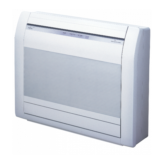
Fujitsu AGYG09LVCA Installation Manual
Indoor unit floor type
Hide thumbs
Also See for AGYG09LVCA:
- Service manual (38 pages) ,
- Design & technical manual (425 pages) ,
- Service manual (80 pages)
Table of Contents
Advertisement
Quick Links
AIR CONDITIONER
INDOOR UNIT
Floor Type
INSTALLATION MANUAL
AMP Air Conditioning
INSTALLATION MANUAL
For authorized service personnel only.
INSTALLATIONSANLEITUNG
Nur für autorisiertes Personal.
MANUEL D'INSTALLATION
Pour le personnel agréé uniquement.
MANUAL DE INSTALACIÓN
Solo para personal autorizado.
MANUALE D'INSTALLAZIONE
Ad uso esclusivo del personale autorizzato.
ΕΓΧΕΙΡΙΔΙΟ ΕΓΚΑΤΑΣΤΑΣΗΣ
Για εξουσιοδοτημένο προσωπικό σέρβις.
MANUAL DE INSTALAÇÃO
Apenas para técnicos autorizados.
РУКОВОДСТВО ПО УСТАНОВКЕ
Для уполномоченного персонала.
KURULUM KILAVUZU
Yetkili servis personeli içindir.
PART NO. 9378533028-03
www.ampair.co.uk | sales@ampair.co.uk
Advertisement
Table of Contents

Summary of Contents for Fujitsu AGYG09LVCA
-
Page 1: Installation Manual
AIR CONDITIONER INDOOR UNIT Floor Type INSTALLATION MANUAL INSTALLATION MANUAL For authorized service personnel only. INSTALLATIONSANLEITUNG Nur für autorisiertes Personal. MANUEL D’INSTALLATION Pour le personnel agréé uniquement. MANUAL DE INSTALACIÓN Solo para personal autorizado. MANUALE D’INSTALLAZIONE Ad uso esclusivo del personale autorizzato. ΕΓΧΕΙΡΙΔΙΟ... -
Page 2: Table Of Contents
INSTALLATION MANUAL This mark indicates procedures which, if improperly performed, PART NO. 9378533028-03 might possibly result in personal harm to the user, or damage to CAUTION INDOOR UNIT (Floor Type) property. Read carefully all security information before use or install the air conditioner. Contents Do not attempt to install the air conditioner or a part of the air conditioner by yourself. -
Page 3: For Authorized Service Personnel Only
CONNECTION PIPE REQUIREMENT 2.5. Optional parts WARNING Refer to each installation manual for the method of installing optional parts. Do not use the existing (for R22) piping and fl are nuts. Parts name Model No. Application • If the existing materials are used, the pressure inside the refrigerant cycle will rise Wired Remote Controller UTY-RNN M For air conditioner operation... -
Page 4: Installation Work
80 mm or more 80 mm or more 100 mm or more WARNING Indoor Select installation locations that can properly support the weight of the indoor. Install Upper air outlet unit the units securely so that they do not topple or fall. Grating CAUTION Do not install the unit in the following areas:... -
Page 5: Cutting The Hole In The Wall For The Connecting Piping
WARNING Fasten with Base 5 to 10 mm vinyl tape If the wall pipe is not used, the wire interconnecting the indoor and outdoor units may Wall cap* Wall pipe* touch metal and cause electric leakage. (Inside) (Outside) Wall *Field supplied 6.5. -
Page 6: Indoor Unit Installation
6.9. Flare connection (Pipe connection) DRAIN HOSE WARNING Tighten the flare nuts with a torque wrench using the specified tightening method. Otherwise, the fl are nuts could break after a prolonged period, causing refrigerant to leak and generate hazardous gas if the refrigerant comes into contact with a fl ame. 6.9.1. -
Page 7: Electrical Wiring
Tighten with two wrenches. 7.3. How to connect wiring to the terminals Indoor unit pipe Wrench (fi xed) Caution when wiring cable When stripping off the insulation of a lead wire, always use a special tool such as a wire Flare nut stripper. -
Page 8: Test Run
Check the following: Remote controller holder fi xing Remote controller mounting GOOD NO GOOD NO GOOD (1) Set Accumulated No upward Remote controller Stopping drain water slope holder downward (2) Push Tapping screw NO GOOD NO GOOD NO GOOD Remote (small) End of drain hose No upward... -
Page 9: Side Panel L And Control Cover Removal
12. FUNCTION SETTING 11.4. Side panel L and control cover removal Perform the “FUNCTION SETTING” according to the installation conditions using the remote controller. (1) Refer to “6.3. Side panel L, R removal and installation” to remove the side panel L. (2) Remove the control cover. -
Page 10: Customer Guidance
(♦... Factory setting) CAUTION Setting Description Function Number Setting Value After turning off the power, wait 10 seconds or more before turning on it again. The Function Setting does not become active unless the power is turned off then on ♦... -
Page 11: Error Codes
Current sensor error 14. ERROR CODES If you use a wireless remote controller, the lamp on the photo detector unit will output • Discharge pressure sensor error error codes by way of blinking patterns. If you use a wired remote controller, error codes •...


